Click here for a higher resolution (larger) schematic.
Introduction:
The local oscillator is the heart of the converter. It is the most critical
circuit in the converter because any drift or instability in the local
oscillator will translate into drift and instability in the output signal. The
use of a crystal controlled local oscillator guarantees the oscillator will be
absolutely stable.
In the 6x2C converter the local oscillator operates at either 3.146 MHz or
10.24 MHz.
With the 3.146 MHz crystal, signals in the 30m band, 10,100 kHz to 10,150 kHz,
are converted to 6,954 kHz to 7,004 kHz in the 40m band.
With the 10.240 MHz crystal signals in the 20m band, 14,000 kHz to 14,090 kHz,
are converted to 3,760 kHz to 3,850 kHz in the 80m band.
The unusual crystal and output frequencies are caused by the crystals I had to
use. They were the only ones I could find.
Local Oscillator
Circuit
Click On Any Part Of The Picture Below For
Information On That Part Of The Circuit

Click On Any Part Of The Picture Above For
Information On That Part Of The Circuit
| B+ Plate Voltage |
| Plate Dropping Resistor |
| Plate Bypass Capacitor |
| Band Switch |
| Plate Coils and Capacitors |
| Output Coupling Capacitor |
| 6GH8 Vacuum Tube |
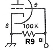
| Grid Leak |
| Crystals |
| Plate Bypass Capacitor: The plate bypass capacitor assures that the power supply side of L3 and L4 is at RF ground. |
 |
| Band Switch: The band switch is a double pole two position switch. Pole S2A (shown here) selects the correct plate coil and capacitor.. The other section, pole S2B, selects the correct crystal. |
 |
| Output Coupling Capacitor: The output of the local oscillator is coupled to the grid of the mixer through a 10 pf capacitor. |
 |
| 6GH8 Vacuum Tube: The 6GH8 was originally designed for use in the horizontal deflection circuitry of television receivers. Previous experience with it has shown that it is ideal in this application. The triode is used as the local oscillator, and the pentode is used as the mixer. The two sections are internally shielded from each other. Click here for a 6GH8A data sheet . The 6U8 can be used in this application as well. It is a direct plug in replacement. No circuit modifications are needed. The 6GH8 may provide slightly better gain and improved resistance from pulling on strong signals, but the 6U8 should still work fine. Click here for a .6U8A data sheet. |
 |
| Crystals: The band switch is a double pole two position switch. Pole S2B (shown here) selects the correct crystal. The other section, pole S2A, selects the correct plate coil and capacitor. With the 3.146 MHz crystal, signals in the 30m band, 10,100 kHz to 10,150 kHz, are converted to 6954 kHz to 7004 kHz in the 40m band. With the 10.24 MHz crystal signals in the 20m band, 14,000 kHz to 14,090 kHz, are converted to 3760 kHz to 3850 kHz in the 80m band. The unusual crystal and output frequencies are caused by the crystals I had to use. They were the only ones I could find. |

|
 Back to Dr.
Greg Latta's Electrical Engineering and Amateur Radio Pages
Back to Dr.
Greg Latta's Electrical Engineering and Amateur Radio Pages
 If you have any questions or
comments, you can send E-Mail to Dr. Greg Latta at
glatta@frostburg.edu
If you have any questions or
comments, you can send E-Mail to Dr. Greg Latta at
glatta@frostburg.edu