Click here for a higher resolution (larger) schematic.
Introduction:
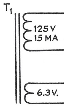
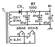
The 6x2C converter draws very little B+ current. As a result, the B+ power
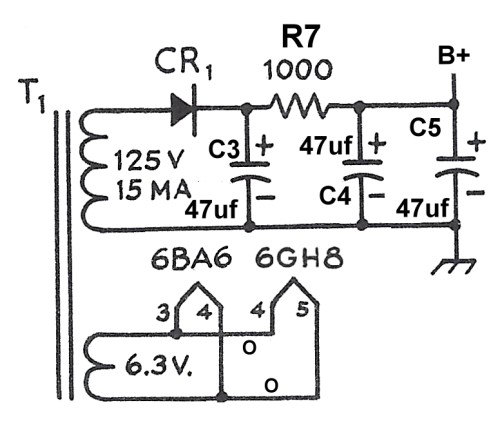
supply uses a simple half wave rectifier. The output is smoothed by a pi filter
consisting of three filter capacitors and a resistor. The tube filaments are
powered by a 6.3V AC winding on the transformer.
B+ Power Supply
Circuit
Click On Any Part Of The Picture Below For
Information On That Part Of The Circuit
Click On Any Part Of The Picture Above For
Information On That Part Of The Circuit
| Power Transformer Secondaries |
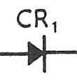
| Rectifier Diode |
| Pi Section Filter |
| Tube Filaments |
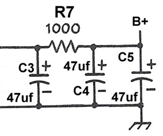
| Pi Section Filter: The output from the rectifier diode is direct current (DC) but with a large alternating current (AC) component superimposed. A pi section filter removes the AC component providing clean DC. Input capacitor C3 does an initial job of smoothing out the pulsations from the rectifier. The current then "leaks through" resistor R7 to the output capacitor consisting of capacitors C4 and C5 in parallel. These remove any remaining pulsations and provide smooth DC to the converter B+ circuits. The capacitors are rated at 200V. I used two 47uf units (C4 and C5) in parallel for a total of 94uf because I had them on hand. A single 100uf unit in place of C4 and C5 would work here just as well.. |
 |
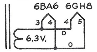
| Tube Filaments: 6.3V tubes are used in the 6x2C converter. The filaments draw a total of 0.75A. A single 6.3V winding on the transformer supplies the required current. |
 |
 Back to Dr.
Greg Latta's Electrical Engineering and Amateur Radio Pages
Back to Dr.
Greg Latta's Electrical Engineering and Amateur Radio Pages
 If you have any questions or
comments, you can send E-Mail to Dr. Greg Latta at
glatta@frostburg.edu
If you have any questions or
comments, you can send E-Mail to Dr. Greg Latta at
glatta@frostburg.edu