Click here for a higher resolution (larger) schematic.
Introduction:
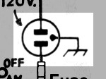
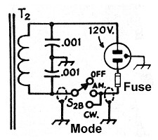
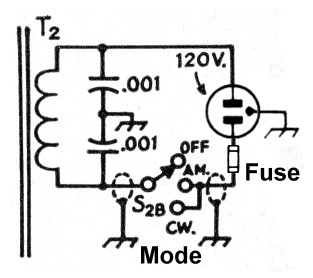
The primary wiring of the 6x2 receiver is straightforward. A grounded 3-wire
cord supplies power and keeps the chassis grounded at all times in case of a
component failure. A fuse protects against excessive current draw, and a power
switch, part of the Mode switch, applies primary power in the AM and CW modes.
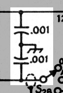
Two bypass capacitors also shunt each side of the AC line to ground to prevent
any RF from entering or leaving via the line cord. (RF leaving via the line
cord could include oscillator harmonics that could cause TVI, and RF entering
via the line cord could include RF from the transmitter.)
AC Primary
Circuit
Click On A Section of the Schematic
Below for Information on That Part of the Circuit:
| 3-Wire Grounded Cord |
| Fuse |
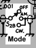
| Mode Switch |
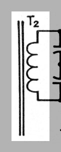
| Power Transformer Primary |
| RF Bypass Capacitors |
| Fuse: A fuse in the hot lead of the AC supply protects against excessive current draw that could damage components or start a fire. |
 |
| Mode Switch: One section of the Mode switch is used as a power switch. Power is applied to the transformer primary in the AM and CW positions of the switch. |
 |
 Back to Dr.
Greg Latta's Electrical Engineering and Amateur Radio Pages
Back to Dr.
Greg Latta's Electrical Engineering and Amateur Radio Pages
 If you have any questions or
comments, you can send E-Mail to Dr. Greg Latta at
glatta@frostburg.edu
If you have any questions or
comments, you can send E-Mail to Dr. Greg Latta at
glatta@frostburg.edu