
6x2 Input Network
| Introduction |
| Redraw The Schematic |
| How An Alternate Circuit With Four Inductors Works |
| Purpose Of C1a |
| It's The Same Circuit |
| Double Resonance |
Introduction:
The input network of the 6x2 receiver was taken from a receiver that was
originally described in the 1965 ARRL Handbook. The circuit is designed to pass
either the 80m band or the 40m band, one at a time. To get adequate selectivity
to reject one band while passing the other requires two tuned circuits.
Redraw The Schematic:
I puzzled over how this circuit worked for a very long time. Even though I knew
what it was supposed to do, I couldn't figure it out. The problem is the way
the circuit is drawn. At first glance, it appears to be a couple of
series tuned resonant circuits, but this is absolutely wrong. The secret
to understanding the circuit is to redraw the circuit and rearrange the
components to better illustrate their purpose. In the schematic below, the
crystal calibrator input has been eliminated to avoid confusion and coil L2 has
been moved to the bottom of the schematic diagram and drawn vertically, rather
than horizontally. The circuit is unchanged.
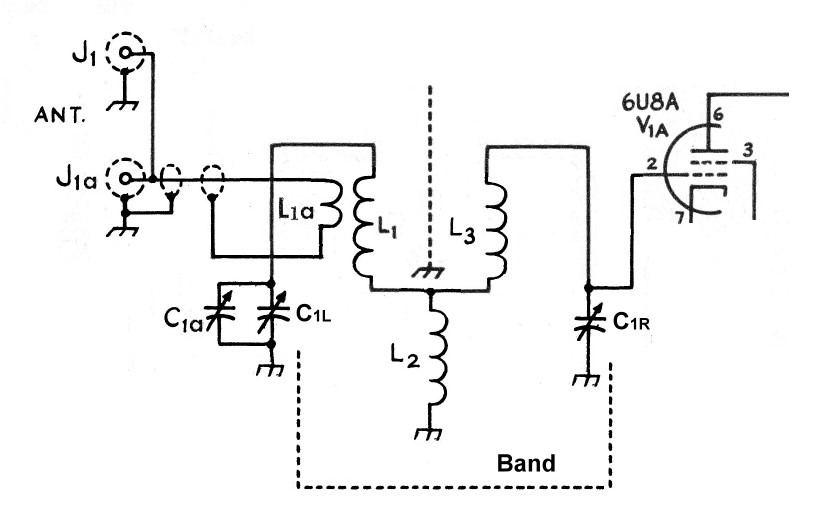
Careful inspection now shows that there are actually two parallel resonant circuits side by side. The left resonant circuit consists an inductor equal to L1 and L2 in series, which is in parallel with C1L. The right resonant circuit consists of an inductor equal to L3 and L2 in series, which is in parallel with C1R.
Note that the inductors L1 and L3 are isolated from each other as indicated by the vertical grounded line between them. They are mounted at right angles to each other so that no magnetic coupling exists between them. They do not form a transformer. The only coupling that can occur is from L2, which is common to both resonant circuits. How L2 couples the two circuits to each other will be explained below, and is the key to understanding how the whole circuit operates.
How An Alternate Circuit With Four Inductors
Works:
To understand how the circuit operates, first consider the alternate circuit
below, consisting of four inductors rather than three:

In this circuit, two inductors, LA and LB, are used for each resonant circuit. However, LB has less inductance than LA. Two two inductors in series form a single inductor that is tapped at the junction of LA and LB. By changing the value of LB we can effectively change the position of the tap. Also note that the two coils LA and LB are not magnetically coupled to each other. They are mounted in different locations so that their magnetic fields do not interact.
Energy from the antenna is fed into the left resonant circuit through a link coupling, L-link. The transformer action of L-link and LA steps up the voltage from the low impedance antenna to the high impedance resonant circuit. When C1 is adjusted to the desired band, maximum signal voltage will build up across the parallel resonant circuit of LA + LB and C1L. Some of this signal is sampled from the tap at the junction of LA and LB. The signal is taken from the tap so that the circuit is not excessively loaded, which would ruin its selectivity.
This signal is then fed to the resonant circuit on the right, which is identical to the left resonant circuit. Again, the signal is fed in through the tap at the junction of LA and LB so that the circuits are lightly coupled, maintaining the selectivity of each. The output signal is then taken across C1R. The tube only lightly loads the right circuit because the input impedance of the tube is very high.
To summarize: In the above circuit the input signal from the antenna passes through two lightly coupled parallel resonant circuits before reaching the mixer. The two circuits together have enough selectivity to pass one band while effectively rejecting the other.
Purpose Of C1a:
Since the grid of the mixer circuit (6U8A) is placed in parallel with C1R,
the two resonant circuits will not track correctly unless extra capacitance
is placed across C1L to compensate. This is accomplished by placing a small
trimmer capacitor (C1a) across C1L. In practice, C1 is adjusted for a peak in
the signal and then C1a is adjusted for a maximum response. The two circuits
will then track properly.
It's The Same Circuit:
The above circuit might seem different from the actual circuit in the 6x2, but,
in fact, it is exactly the same. Since the two inductors labeled LB in the
figure above are in parallel, they can be replaced with a single
inductor having half the value of each. This inductor is L2. Likewise,
the inductors labeled LA can be replaced with L1 and L3 so that we obtain the
following circuit, which is the same as the circuit in the 6x2 receiver:
The above circuit saves the builder the trouble of having to wind two identical tapped coils, or of winding four individual coils. Instead, only three easy to wind coils are needed, two of which can be cut from commercial Miniductor or AirDux stock.
Double Resonance:
In practice, it is found that the above circuit exhibits two resonances
on each band, even when C1a is correctly adjusted. On each band, one
resonance is stronger and occurs with a larger capacitance for C1. In practice,
and contrary to intuition, the band control should be set to the weaker of
the two peaks (smaller capacitance for C1), as will be explained below.
The second resonance occurs because there is also a resonant circuit formed by
L1, L3, C1L, and C1R. If you start at the junction of L1, L2, and L3, and
progress clockwise through L3, C1R, C1L, and L1, you will see that these are
all in series, with the junction between C1R and C1L grounded. The
effective inductance of this circuit is L1 + L3 (twice L1 or L3) and the
effective capacitance is the capacitance of C1L and C1R in series (half of C1L
or C1R). The resonant frequency of this circuit is thus the same as a circuit
formed by L1 and C1L alone or L3 and C1R alone.
Since the effective inductance (L1) of this resonant circuit is smaller
than the inductance of the desired resonant circuits (L1 + L2 or L3 + L2), it
occurs at a larger capacitance setting of C1. The coupling between the
antenna and the mixer input is stronger with this resonance, but as a result,
the selectivity and ability to reject the unwanted band is not as good.
Counter to what one might suppose, this resonance should be avoided.
When tuning C1 to select a given band, use the weaker resonance,
rather than the stronger! The receiver has more than enough gain
to make up for the weaker response, and the weaker resonance has better
selectivity to reject signals in the undesired band.
 Back to Dr.
Greg Latta's Electrical Engineering and Amateur Radio Pages
Back to Dr.
Greg Latta's Electrical Engineering and Amateur Radio Pages
 If you have any questions or
comments, you can send E-Mail to Dr. Greg Latta at
glatta@frostburg.edu
If you have any questions or
comments, you can send E-Mail to Dr. Greg Latta at
glatta@frostburg.edu