Click here for a higher resolution (larger) schematic.
Introduction:
The B+ power supply uses the standard, full wave center-tapped configuration. A
5Y3-GT (or a pair of 1N1007 silicon diodes, if desired) is used as the
full-wave rectifier. The output is smoothed by a pair of filter capacitors and
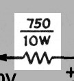
a filter choke. A series dropping resistor drops the output of the supply to
250V.
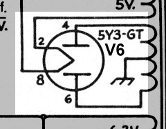
The 5Y3-GT rectifier filament is powered by a separate 5V AC winding on the
power transformer, and the tube filaments and dial lamps are powered by another
6.3V AC winding.
B+ Power Supply
Circuit
Click On A Section of the Schematic
Below for Information on That Part of the Circuit:

| Power Transformer Secondary |
| 5Y3-GT Vacuum Tube |
| Filter Capacitors |
| Filter Choke |
| Voltage Dropping Resistor |
| Tube Filaments |
| Dial Lamps |
| 5Y3-GT Vacuum Tube: The transformer steps up the 120 volts AC in the primary to 540 volts AC in the secondary. When the top connection to the secondary is positive with respect to the bottom connection and center tap, the upper diode of the 5Y3-GT rectifier tube (pins 4 and 2/8) conducts, allowing current to pass to the output. During this time the bottom diode (pins 6 and 2/8) is cut off. When the bottom of the secondary is positive with respect to the top and center tap the opposite is true: the upper diode is cut off and the bottom diode conducts. The result is a stream of DC pulses at pin 8, the output of the rectifier. The output is then fed to the power supply filter, which consists of two 47uf filter capacitors and a 10H filter choke. The 5 volt secondary provides the 5 volts needed to heat the filament/cathode of the rectifier tube. The 5Y3-GT is one of the most popular full wave rectifiers. With two diodes in a single envelope, and an output capability of about 125mA, it is perfectly suited for use in receivers and other equipment with moderate power requirements. You can click here for a 5Y3-GT tube data sheet . |
 |
| Filter Capacitors: The output from the 5Y3-GT vacuum tube is direct current (DC) but with a large alternating current (AC) component superimposed. The two 47uf filter capacitors are essentially an open circuit to the DC, but they effectively short circuit the AC component to ground. Any remaining AC component is blocked by the filter choke. The result is that little of the AC component reaches the output. |
 |
| Tube Filaments: 6.3V tubes are used throughout the 6x2 receiver. The filaments of the 12AX7 first audio tube, which can be wired for either 6.3V or 12.6V operation, are wired in parallel for 6.3V operation. A single 6.3V winding on the transformer supplies the filaments and the dial lamps. |
 |
 Back to Dr.
Greg Latta's Electrical Engineering and Amateur Radio Pages
Back to Dr.
Greg Latta's Electrical Engineering and Amateur Radio Pages
 If you have any questions or
comments, you can send E-Mail to Dr. Greg Latta at
glatta@frostburg.edu
If you have any questions or
comments, you can send E-Mail to Dr. Greg Latta at
glatta@frostburg.edu