Click On A Section of the Schematic
Below for Information on That Part of the Circuit:
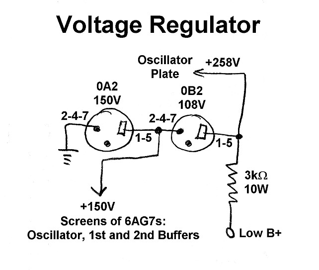
General Information On The Power Supply Voltage Regulator:
The power supply voltage regulator provides a source of regulated voltage for
the plate of the oscillator tube and the screens of the oscillator, 1st buffer,
and 2nd buffer.
Regulated voltage on the oscillator is necessary for good stability and keying,
and regulated voltage on the 1st and 2nd buffers is necessary since they are
operated at higher than normal plate voltages. Keeping the screen voltages
constant also improves the overall keying of the transmitter.
The voltage regulator uses two gaseous regulator tubes, an 0A2 and an 0B2. These tubes have the property that if the current through them is between 5mA and 30mA the voltage across them is constant. The 0A2 regulates at 150V, and the 0B2 at 108V. The two tubes are placed in series and act as a single 258V tube with a tap at 150V.
Power Supply Voltage
Regulator
Click On A Section of the Schematic
Below for Information on That Part of the Circuit:
| 0A2 VR Tube |
| 0B2 VR Tube |
| Series Dropping Resistor |
| 0A2 VR Tube: The 0A2 is a 150V gaseous regulator tube. As long as the current passing through the tube is between 5mA and 30mA the voltage across the tube will be 150V. The screens of the oscillator and 1st and 2nd buffers are connected across the tube. When the key is up, they draw no current and the current in the tube is near the maximum of 30mA. When the key is down and the screens draw current, the current through the tube decreases by just the right amount to compensate and keep the voltage at 150V. You can click here for an 0A2 data sheet. |

|
| 0B2 VR Tube: The 0B2 is a 108V gaseous regulator tube. As long as the current passing through the tube is between 5mA and 30mA the voltage across the tube will be 108V. The 0B2 is connected in series with the 0A2, effectively giving the equivalent of a 258V regulator tube. In a series combination, the current does not need to be the same in each tube. As long as the current in each tube is between 5mA and 30mA, the voltage across the combination will be 258V. The oscillator is connected across the two tubes, so the voltage on the oscillator will also be 258V. When the key is up, only the regulator tubes draw current, and the current in each tube is near the maximum of 30mA. When the key is down and the oscillator plate and the screens draw current, the current through the regulator tubes drops down by just the right amount to compensate and keep the voltage across each tube, and the series combination, at the correct value. You can click here for an 0B2 data sheet. |
 |
 Back to Dr.
Greg Latta's Electrical Engineering and Amateur Radio Pages
Back to Dr.
Greg Latta's Electrical Engineering and Amateur Radio Pages
 If you have any questions or
comments, you can send E-Mail to Dr. Greg Latta at
glatta@frostburg.edu
If you have any questions or
comments, you can send E-Mail to Dr. Greg Latta at
glatta@frostburg.edu
