Schematic Diagram and Circuit Description
Click On A Section of the Schematic
Below for Information on That Part of the Circuit:

Variable Regulated Screen Voltage On Final Amplifier:
When a transmitter is used by itself, the transmitter is almost always run at
full output. However, when the transmitter is used to drive an amplifier, some
method of decreasing the output of the transmitter is often desirable.
Most class C RF amplifiers use grid leak bias and get their screen voltage
through a dropping resistor connected to the plate B+ supply. The screen
dropping resistor is selected to provide proper screen voltage at full output.
This is an excellent way to run an amplifier, but problems can occur when less
than full output is desired.
One way to get less output is to decrease the loading on the amplifier.
However, this provides only a limited amount of control and can result in
excessive screen current in screen grid tubes.
If the drive to such an amplifier is decreased in an attempt to decrease
the output, problems occur because the grid leak bias decreases. This causes
the tube to overheat, even though it is producing less output!
In the Wingfoot Exciter, full drive is kept on the output tube at all times,
which keeps the grid leak bias at the proper value. During key up, blocking
bias is applied to the tube to cut it off. Output power control is provided by
varying the screen voltage on the final amplifier tube. The screen voltage to
the final amplifier is provided through one section of a 12AU7 that functions
as an adjustable voltage regulator. The screen voltage can be smoothly varied
by changing the bias on the regulator tube using the output
("Screen") control.
With this arrangement, the voltage on the screen can be set at about any
desired value and varies less than 11% between key up and key down. This
prevents output spikes during keying, common with other RF amplifiers, that
give the keying a harsh sound. Using the output ("Screen") control,
the output of the Wingfoot Exciter can be smoothly varied from less than 3
watts up to the full output of 27 watts.
Screen Clamp Tube:
The clamp tube protects the final amplifier tube in case drive is lost while
the key is down, or in case blocking bias is lost while the key is up. The grid
of the clamper tube is connected to the
bias on the
final amplifier tube. The presence of either grid-block or operating bias
cuts off the clamper tube, and it has no effect. However, if bias is lost at
any time, the clamper tube turns on, removing the positive voltage at the top
of the output control. This turns down the screen voltage regulator, lowering
the screen voltage. This lowers the final amplifier plate current, protecting
the tube.
Screen Voltage Regulator and Clamp
Tube
Schematic Diagram and Circuit Description
Click On A Section of the Schematic
Below for Information on That Part of the Circuit:
| Grid Bias Input From Final Amplifier |
| Clamp Tube Grid Capacitor |
| 12AU7 Tube |
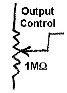
| Output Control |
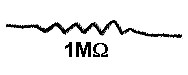
| Output Control Dropping Resistor |
| Cathode Bias Resistor/Load Resistor |
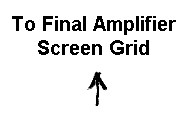
| Output To Final Amplifier Screen Grid |
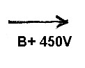
| Low B+ |
| Grid Bias Input From Final Amplifier: The clamp tube protects the 2E26 final amplifier in the event that bias is lost. This could occur several ways: 1. Loss of drive while the key is down. This could occur due to a problem in any of the earlier circuits on the signal chain. 2. Loss of cutoff bias while the key is up due to a failure in the bias power supply. The bias on the final amplifier tube is fed via this connection to the grid of the clamper tube. As long as bias is present, the clamper tube is cutoff and has no effect. But if bias is lost, the clamper tube turns on, essentially shorting the voltage at the top of the output control to ground. This increases the bias on the screen voltage regulator and drops the screen voltage to a low value, protecting the final amplifier tube. |
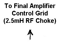 |
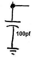
| Clamp Tube Grid Capacitor: The clamp tube grid capacitor shorts to ground any residual RF that may be present at the grid of the tube. The value of this capacitor is not critical. |
 |
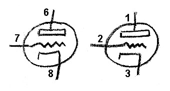
| 12AU7 Tube: The 12AU7 is a rugged, low gain (u), dual triode. The plate dissipation for each section is 2.75 watts, which is very good given the small size of the 12AU7. The 12AU7 has an amplification factor (u) of about 17 and a transconductance of about 2200 umhos. The 12AU7A and 5814A are electrically equivalent to the 12AU7 and can be used instead of the 12AU7. High gain is undesirable in this circuit, since the tube is being used only as a voltage regulator and switch. Excessive gain could lead to undesirable self oscillation. You can click here for a 12AU7A data sheet. |
 |
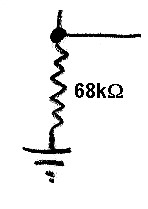
| Output Control: The output control dropping resistor and the output control form a voltage divider connected across the low B+ power supply. By turning the output control, a voltage from zero up to one half of the low B+ supply voltage can be selected. The bias on the grid of the screen regulator tube is a combination of the positive voltage from the output control and the negative voltage from the cathode bias/load resistor. By turning this control, the bias and current through the screen regulator tube can be varied. This changes the voltage across the cathode bias/load resistor and the final amplifier screen grid, which is connected across the cathode bias/load resistor. |
 |
| Output Control Dropping Resistor: The output control dropping resistor is in series with the output control and limits the voltage at the top of the output control to one half of the low B+ supply voltage. This resistor also limits the current flowing through the clamper tube to a safe value, should the clamper tube turn on. |
 |
| Output To Final Amplifier Screen Grid: The final amplifier screen grid is connected across the cathode bias/load resistor via this connection. The voltage across the cathode bias/load resistor is adjustable and is held relatively constant by the action of screen regulator tube. By turning the output control, the transmitter output can be smoothly varied from about 3 watts to 27 watts. |
 |
| Low B+: The screen regulator is powered by the low B+ power supply in the Wingfoot VFO Exciter. This supply has an output of about 450V. |
 |
 Back to Dr.
Greg Latta's Electrical Engineering and Amateur Radio Pages
Back to Dr.
Greg Latta's Electrical Engineering and Amateur Radio Pages
 If you have any questions or
comments, you can send E-Mail to Dr. Greg Latta at
glatta@frostburg.edu
If you have any questions or
comments, you can send E-Mail to Dr. Greg Latta at
glatta@frostburg.edu