Click here for a higher resolution (larger) schematic.
Introduction:
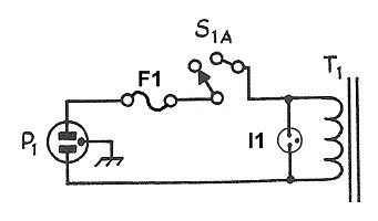
The primary wiring of the 6x2C crystal controlled converter is straightforward.
A grounded 3-wire cord supplies power and keeps the chassis grounded at all
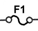
times in case of a component failure. A fuse protects against excessive current
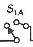
draw, and a power switch, section S1A of the Mode switch, applies primary power
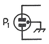
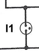
in the Standby and Run modes. A pilot light that matches the one on the
6x2 receiver indicates when the
power is on.
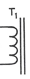
The transformer is a small unit salvaged from a gutted Heathkit VTVM.
Important Note:
The original schematic shows the power from the cord first passing through the
mode switch, then through the fuse. However, good engineering practice dictates
that the power from the cord should pass first through the fuse, then
through the switch. The actual wiring follows good engineering practice, and
the schematic on this page has been changed to show the correct, actual, power
wiring.
AC Primary
Circuit
Click On Any Part Of The Picture Below For
Information On That Part Of The Circuit

Click On Any Part Of The Picture Above For
Information On That Part Of The Circuit
| 3-Wire Grounded Cord |
| Fuse |
| Mode Switch |
| Pilot Light |
| Power Transformer Primary |
| Fuse: A fuse in the hot lead of the AC supply protects against excessive current draw that could damage components or start a fire. |
 |
| Mode Switch: One section of the Mode switch is used as a power switch. Power is applied to the transformer primary in the Standby and Run positions of the Mode switch. |
 |
| Pilot Light: A pilot light indicates when power is applied to the converter. The pilot light is the same as that used on the 6x2 receiver. |
 |
 Back to Dr.
Greg Latta's Electrical Engineering and Amateur Radio Pages
Back to Dr.
Greg Latta's Electrical Engineering and Amateur Radio Pages
 If you have any questions or
comments, you can send E-Mail to Dr. Greg Latta at
glatta@frostburg.edu
If you have any questions or
comments, you can send E-Mail to Dr. Greg Latta at
glatta@frostburg.edu