Click on the image for a larger view. Click here for a super detailed view. |
 Click on the image for a larger view. Click here for a super detailed view. |
|
Click on the image for a larger view. Click here for a super detailed view. |
Click on the image for a larger view. Click here for a super detailed view. |
| 6x2 Receiver - Main Page and Exterior Photos | Schematic Diagram and Circuit Descriptions |
| Interior Photos | Alignment |
| How To Operate The 6x2 Receiver | Parts and Construction |
| Greger Warna's Receiver | Mechanical Construction |
Introduction and Historical Background:
The 6x2 superheterodyne receiver is a 6 tube, 2 band receiver for 80m and 40m with a special position for receiving WWV at 5 MHz. Modes are CW, SSB, and AM, The receiver features a powerful 4 watt audio amplifier, crystal filter for single-signal reception, and 100 kHz crystal calibrator. Gain control is manual. There is no AGC or S-meter, as these would have greatly complicated the design. An external mute circuit is provided to mute the receiver IF amplifier during transmission.
The receiver design is based on several different previous designs. The front end band-select circuit and crystal filter are taken from a 1965 ARRL Handbook receiver. The mixer, local oscillator, IF amplifier, BFO, and detector are taken from a 1961 ARRL Handbook receiver. The powerful audio section is my design, and the crystal calibrator is taken from the 1965 Drake R4A receiver. The power supply is taken from the 1961 Handbook receiver, with appropriate changes to accommodate my power transformer.
Though solid state diodes could have been used in the power supply, I wanted an authentic, all tube receiver, so an octal tube socket was used in the power supply for the rectifier. The octal socket allows the use of either a 5Y3-GT tube for authenticity or a set of plug in 1N4007 diodes (in an octal socket) for performance. I usually use the 5Y3-GT, as this was used in designing the receiver and produces the desired B+ voltage.
The receiver is very sensitive with low noise and plenty of gain. The IF gain is typically run near its minimum setting. Even an 8 foot wire connected to the input raises the noise level in the output on 80m, showing that the receiver self noise is quite low, especially for the 80m and 40m bands. In typical operation, with the IF gain control near its minumum setting, disconnecting the antenna results in complete silence from the receiver.
The receiver is very stable after about 45 minutes of warm-up (typical of vintage receivers) and exhibits single-signal selectivity, with a compromise bandwidth narrow enough for adequate CW reception but wide enough to also work well on SSB. Selectivity for CW is greatly improved by using an external audio filter. (This is true for most vintage receivers.) Performance on AM is not the best because of the limited selectivity, but AM is only used in receiving WWV at 5MHz.
The audio amplifier has an output of 4w and will drive any speaker. The high frequency response of the the audio amplifier is rolled off to reduce noise and improve signal readability. Either low or high impedance headphones can be used. (When low impedance headphones are used, a series dropping resistor of about 1k ohm will improve performance.
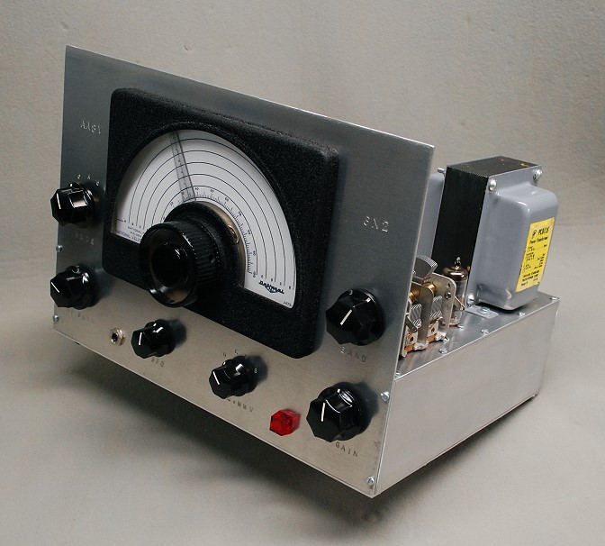
| Front View: The 6x2 receiver is a 6 tube (not counting rectifier and voltage regulator), 2 band superheterodyne receiver that covers the 80m and 40m amateur radio bands. A special WWV function is also available that permits the reception of WWV at 5 MHz. The receiver exhibits single signal reception and can receive AM, CW, and SSB signals. The 6x2 covers 3.5 MHz to 3.84 MHz in the 80m band, 6.9 MHz to 7.24 MHz in the 40m band, and 5.0 MHz to 5.1 MHz in the 60m band. Bandswitching between the 80m and 40m bands is done by changing the setting of a variable capacitor (BAND control). The WWV band is obtained by rotating the CAL.WWV control to either W (WWV Only) or B (Both WWV and Calibrate). An RF amplifier is not used in the 6x2 receiver since it is unnecessary on frequencies below about 7 MHz and needlessly adds to the complexity and cost of the receiver. Even without the RF amplifier, the receiver can easily pick up the background noise in an 8 foot piece of wire. (On air use has shown that it picks up QRP stations on both 80m and 40m with ease.) The receiver has good selectivity, obtained by using a crystal filter in the 1700kHz IF amplifier. The gain of the receiver is controlled manually by varying the gain of the IF amplifier and the audio gain. It does not have automatic gain control (AGC). |
Click on the image for a larger view. Click here for a super detailed view. |
| Right Side View: The receiver is powered by a Stancor PC8405 power transformer. As can be read from the yellow label in the picture, the transformer is rated at 540V CT at 120mA, 5V at 3A, and 6.3V at 3.5A. I was lucky enough to run into a cache of these and bought about five of them at the same time! This size transformer was perfect for the 6x2 receiver. Just to the left of the power transformer is the 6BA6 crystal calibrator. The calibrator trimmer capacitor and 100kHz crystal are visible just behind the tube. The 2-gang band change variable capacitor can be seen on the left, just behind the front panel. This control tunes the input bandpass circuit to either 80m, 60m (WWV), or 40m. |
Click on the image for a larger view. Click here for a super detailed view. |
| Front Panel Detail: This is a straight view of the receiver front panel. The main tuning dial is a National type ICN illuminated tuning dial. The dial has not yet been calibrated in this photo. Other control functions, clockwise from the upper right, are: Band: Clockwise=Higher Frequency IF Gain: Clockwise=Higher Gain CALibrate/WWV: O (Off), C (Calibrate Only), W (WWV Only), B (Both) BFO: Clockwise=Higher BFO Frequency AF Gain: Clockwise=Higher Gain Mode: O (Off), A (AM), C (CW/SSB) |
 Click on the image for a larger view. Click here for a super detailed view. |
| Early Front View On The Workbench: This is a picture of the finished receiver while it sits on the workbench undergoing testing. The front dial has not yet been calibrated. The panel controls are as follows: Upper Left: Mode - Off, AM, CW/SSB Lower Left: Audio Gain (Volume) Upper Right: Band Selector Lower Right: IF Gain Bottom Left Small Knob: BFO Pitch Bottom Right Small Knob: Calibrate/WWV: Off, Calibrate, WWV, Both |
 Click on the image for a larger view. |
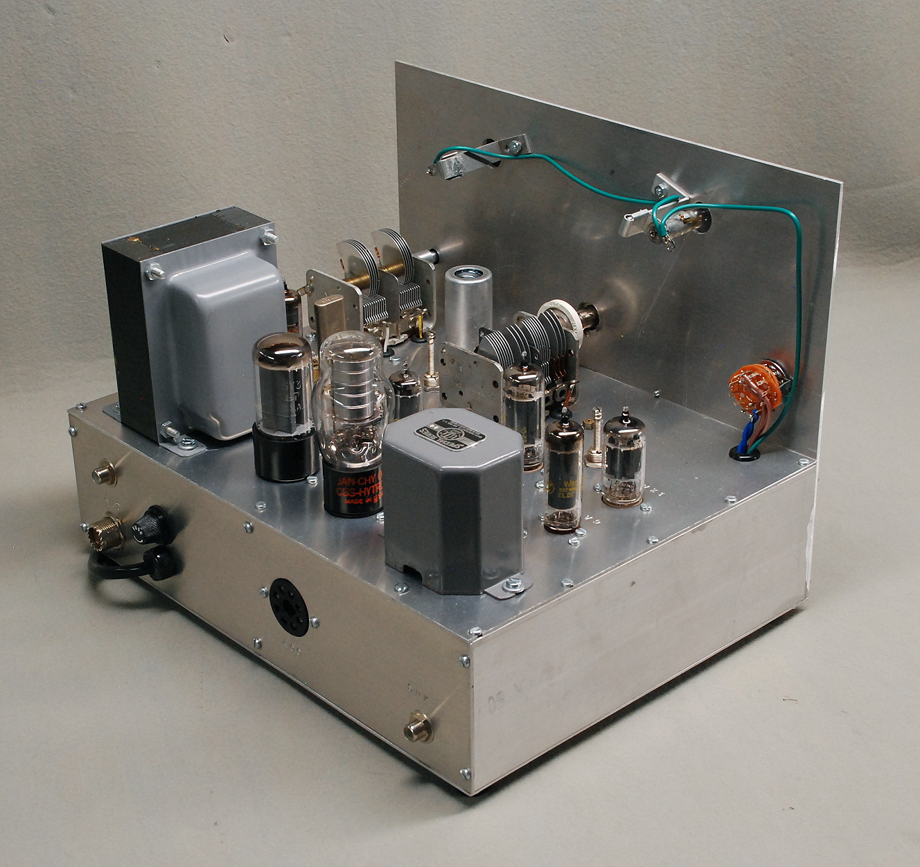
| Rear View #1: The heaviest components are at the back of the receiver. In this picture the power transformer is on the left and the audio output transformer is on the right. The power supply tubes are in the middle, between the transformers. Though solid state diodes could have been used in the power supply, I wanted an authentic, all tube receiver, so an octal tube socket was used in the power supply for the rectifier. The octal socket allows the use of either a 5Y3-GT tube for authenticity or a set of plug in 1N4007 diodes (in an octal socket) for performance. I usually use the 5Y3-GT, as this was used in designing the receiver and produces the desired B+ voltage. The OC3 voltage regulator tube lies to the right of the 5Y3. When both tubes are in use they produce a nice, satisfying glow. |
 Click on the image for a larger view. Click here for a super detailed view. |
| Early Rear View On The Workbench: In this rear view of the receiver the power transformer is at the top left. Immediately to the right of the power transformer are the 6BA6 crystal calibrator and the 100 kHz calibrator crystal. At the top on the right, just behind the front panel, is the dual section band select capacitor. The 5Y3-GT rectifier tube and 0C3 regulator tube can be seen on the left in the photo. In the center of the picture are the 1700 kHz FT-243 quartz crystal (brown) and phasing capacitor (white) that make up the crystal filter. These are plugged into an octal socket. Just below them is the 6BA6 IF amplifier tube. To the right (with tube shield) is the 6U8A local oscillator/mixer tube, and the main tuning capacitor is just below it. Only the front 35pf section of the tuning capacitor is used. Just below the main tuning capacitor is the 6CG7 detector/BFO tube. At the very bottom of the photo on the left the audio output transformer is barely visible, and to its right are the 6AQ5 audio output and 12AX7 audio preamp tubes. |

Click on the image for a larger view. |
| Rear View #2: The 6x2 receiver uses a high quality audio amplifier with 4 watts of undistorted output. This is made possible by a robust power supply and the high quality UTC-S14 output transformer, which is front and center in this rear view of the receiver. The 6AQ5A audio output tube is just to the right of the transformer, and the 12AX7 audio preamplifier tube is to the right of the 6AQ5A. Only one section of the 12AX7 dual triode is used, since more gain is not needed. The 6CG7/6FQ7 BFO and detector is just behind the audio tubes, just to the right of the main tuning capacitor. At the back of the photo the 6BA6 crystal calibrator tube is visible just to the right of the power transformer. The calibrator crystal is in front of the 6BA6 and the dual section band select capacitor is to the right of the 6BA6. The 6U8A local oscillator and first mixer is covered with a tube shield and is just to the left of the main tuning capacitor. A flexible coupling (white) is used on the main tuning capacitor to provide smooth tuning with no jerky motion. Though the main tuning capacitor has four sections, only one of the these, the front section, is used. |
 Click on the image for a larger view. Click here for a super detailed view. |
| Early Side View On The Workbench: This is a side view of the receiver. The hi-fi audio section is at the bottom of the photo, and consists of a 12AX7 audio preamplifier and a 6AQ5 power amplifier. The audio output transformer is at the bottom left in the photo. Power output is about 4 watts. The power transformer is at the upper left in the picture. In front of the power transformer are the 5Y3-GT rectifier tube and 0C3 voltage rectifier. The crystal calibrator is in the middle at the top of the photo, and the input tuning capacitor (band selector) is immediately to the right of the crystal calibrator. The mixer, local oscillator, crystal filter, and IF amplifier are in the middle of the photo. A 6U8A (with tube shield) is used as the mixer and local oscillator. The crystal filter is just to the left of the 6U8A and uses a single 1700 kHz FT-243 quartz crystal. The FT-243 crystal and the phasing trimmer capacitor are plugged into an octal socket. A 6BA6 (just to the left of the main tuning capacitor) is used as the IF amplifier, and a 6CG7/6FQ7 (just in front of the left side of the main tuning capacitor) is used as the BFO and detector. |
 Click on the image for a larger view. |
| Rear Panel: The rear panel of the receiver contains the input/output connectors and an accessory socket. The input of the receiver is on the left side of the back panel, and uses either an RCA phono jack or an SO-239 coax connector. It always seemed like my receiver cable had the wrong connector on it, so I decided to use both connectors on the 6x2. These are connected in parallel, and cover most cable situations. Speaker output is at the lower right via an RCA phono jack. An octal accessory jack on the back of the receiver provides 6.3V AC, 250V DC, and 108V DC regulated for use by accessories such as a converter, preselector, or electronic T/R switch. The line cord and a fuse complete the back panel layout. The crystal filter (brown) can just be seen to the right and slightly behind the power transformer. The 6BA6 IF amplifier is slightly behind and directly between the large power supply tubes, near the middle of the picture. The mode switch is the orange switch on the front panel on the right. Wires from the mode switch pass through a grommeted hole in the chassis. The green wire carries power to the lamps that illuminate the front panel. The crystal calibrator components are not visible in this photo because they are behind the power transformer on the left. |
 Click on the image for a larger view. Click here for a super detailed view. |
| Notated Rear View: This is a notated view of the top of the receiver as viewed from the rear. All of the parts mounted on the top of the receiver and their functions are marked. All receiver adjustments that can be made from the top of the receiver are also marked The 6BA6 crystal calibrator is not visible because it is behind the power transformer. Also, the IF adjustment is hard to see. The tip of the IF adjustment is just barely visible behind the top of the OC3 voltage regulator tube. |
 Click on the image for a larger view. Click here for a super detailed view. |
 Back to Dr.
Greg Latta's Electrical Engineering and Amateur Radio Pages
Back to Dr.
Greg Latta's Electrical Engineering and Amateur Radio Pages
 If you have any questions or
comments, you can send E-Mail to Dr. Greg Latta at
glatta@frostburg.edu
If you have any questions or
comments, you can send E-Mail to Dr. Greg Latta at
glatta@frostburg.edu