6x2C Input/Output Switching
(The Mode Switch Is Shown In Off Position)
Circuit Description:
The input/output switching in the 6x2C converter switches the converter circuit
in and out of the receiver antenna line. The Mode switch controls the switching
and also turns the AC power off
and on.
The mode switch is a ceramic Centralab 3 pole-3 position rotary switch. Two of
the poles (S1B and S1C) handle the RF switching, and the other pole (S1A)
handles the AC power
switching.
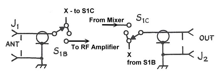
The mode switch has three positions:
Off: The power is off. The antenna (ANT) input is
connected to the output to the receiver (RCV) via S1B and S1C by way of the
connections marked "X" in the diagram. The converter is bypassed.
Standby: The same as the off position except that the
AC power is turned on. The
converter is bypassed.
Run: The AC power is on. The antenna
input (ANT) is connected to the RF amplifier input via S1B. The mixer output is
connected to the converter ouput (RCV) via S1C. The converter is switched in.
This arrangement allows the converter to be quickly switched in and out with
the power on. This makes proper adjustment of the converter and receiver much
easier.
 Back to Dr.
Greg Latta's Electrical Engineering and Amateur Radio Pages
Back to Dr.
Greg Latta's Electrical Engineering and Amateur Radio Pages
 If you have any questions or
comments, you can send E-Mail to Dr. Greg Latta at
glatta@frostburg.edu
If you have any questions or
comments, you can send E-Mail to Dr. Greg Latta at
glatta@frostburg.edu