Click here for a higher resolution (larger) schematic.
Introduction:
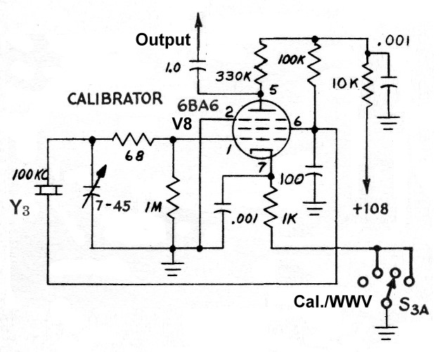
The circuit for the crystal calibrator in the 6x2 receiver was taken straight
from the Drake R4A receiver. The circuit uses a 100kHz crystal in a Pierce
oscillator circuit in an electron coupled configuration. In such a circuit, the
screen grid of a pentode serves as the plate of the oscillator, while the
actual plate circuit is used to amplify the output of the oscillator.
The circuit does not use any L/C resonant circuits so that the output is rich
in harmonics. The result is a circuit that puts out a signal every 100kHz
(0.1MHz) all the way up to 30MHz. For the 6x2 receiver, the calibrator provides
dial marker/calibration signals at 3500kHz, 3600kHz, 3700kHz, and 3800kHz in
the 80m band, and 6900kHz, 7000kHz, 7100kHz, and 7200kHz in the 40m band. It is
also a very convenient and very stable signal source that can be used for
aligning the receiver and adjusting the BFO.
Crystal
Calibrator
Click On A Section of the Schematic
Below for Information on That Part of the Circuit:
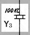
| 100kHz Quartz Crystal: The heart of the crystal calibrator is a 100kHz quartz crystal. The crystal is in an HC13/U hermetically sealed enclosure. |
 |
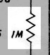
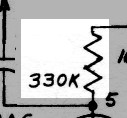
| Grid Leak Resistor: The crystal calibrator uses a combination of grid leak bias and cathode bias. Grid current in the tube flows through the grid leak resistor producing a voltage drop that supplies part of the bias for the tube. The bias is smoothed by the trimmer capacitor, which does double duty as a grid leak capacitor in addition to its primary function. |
 |
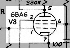
| 6BA6 Vacuum Tube: The 6BA6 tube is used in the crystal calibrator. Many tubes could be used, but the Drake designers chose to use the 6BA6, perhaps because it is used elsewhere in the Drake R4A receiver, from which this circuit was taken. The 6BA6 is also used in the 6x2 receiver in the IF amplifier. Using the same tube makes it easier to keep a spare in stock for backup purposes, so it is a happy coincidence that the same tube is used both in the crystal calibrator and the IF amplifier. You can click here for a 6BA6 tube data sheet. |
 |
| Cathode Bias Capacitor: The RF component of the cathode bias developed across the cathode bias resistor is smoothed by the cathode bias capacitor. Without the capacitor, degenerative feedback would occur, lowering the gain of the stage and lowering the output of the oscillator |
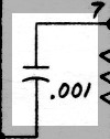 |
| Cathode Bias Resistor: A combination of grid leak bias and cathode bias is used in the crystal calibrator. Current through the cathode bias resistor develops a voltage drop that in part biases the tube. The RF component of the cathode current is smoothed/bypassed by the cathode bias capacitor so that the bias that is developed is constant. |
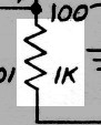 |
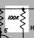
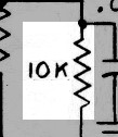
| Plate Load Resistor: The oscillations developed by the oscillator across the control grid are amplified and appear across the plate load resistor, one end of which is grounded for RF through the power supply decoupling capacitor. The signal then passes through the output coupling capacitor to the input of the receiver. |
 |
| Oscillator Load Resistor: The screen grid of the tube is used as the plate of the oscillator. The main output of the oscillator appears across the oscillator load resistor, one end of which is grounded for RF through the power supply decoupling capacitor. The output of the oscillator is fed back through the quartz crystal to the grid of the tube to sustain the oscillations. The quartz crystal acts as a selective feedback element so that the oscillations only occur at the resonant frequency of the crystal. In an electron coupled oscillator, the variations in grid voltage that occur as a result of the oscillation are amplified in the plate circuit and appear across the plate load resistor, which is the main output from the circuit. |
 |
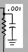
| Power Supply Decoupling Capacitor: To prevent any of the calibrator output from getting into the regulated supply circuit and to keep one end of the plate load resistor and oscillator load resistor at RF ground, a capacitor is connected between the common end of the two load resistors and ground. This, in combination with the power supply isolation resistor, guarantees that the crystal calibrator is well isolated from the regulated power supply. |
|
| Power Supply Isolation Resistor: The power supply isolation resistor, in combination with the power supply decoupling capacitor, guarantees that the crystal calibrator is well isolated from the regulated power supply. |
|
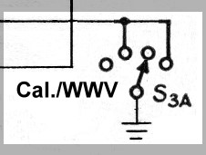
| Calibrate/WWV Switch: The calibrator is turned on by grounding one end of the cathode bias resistor. The calibrator is turned on when the Calibrate/WWV switch is in the 2nd and 4th positions. |
 |
| Output To Receiver: The output of the calibrator is coupled to the receiver input through the output coupling capacitor. Very little signal is needed, since the receiver is very sensitive. |
 |
| Regulated Supply Voltage: It isn't necessary for regulated voltage to be supplied to the calibrator, since the crystal keeps it on frequency, but the 250V plate supply is too high for the calibrator circuit. Instead, the calibrator is supplied from the 108V regulated voltage circuit, which has plenty of current reserve. |
 |
 Back to Dr.
Greg Latta's Electrical Engineering and Amateur Radio Pages
Back to Dr.
Greg Latta's Electrical Engineering and Amateur Radio Pages
 If you have any questions or
comments, you can send E-Mail to Dr. Greg Latta at
glatta@frostburg.edu
If you have any questions or
comments, you can send E-Mail to Dr. Greg Latta at
glatta@frostburg.edu