Click here for a higher resolution (larger) schematic.
Introduction:
The 6x2 local oscillator,
mixer screen grid, and
BFO are sensitive to voltage fluctuations in
their power source. Another circuit, the
crystal calibrator,
needs to run off of a voltage lower than the 250V B+ supply. The voltage
regulator circuit uses an 0C3 regulator tube to provide a source of regulated
voltage at 108V to power these circuits.
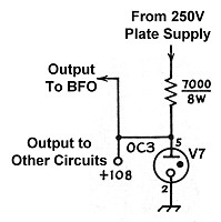
Voltage Regulator
Circuit Circuit
Click On A Section of the Schematic
Below for Information on That Part of the Circuit:
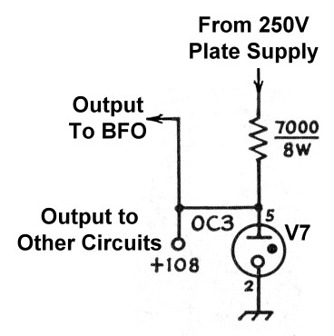
| 0C3 Gaseous Regulator Tube |
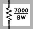
| Regulator Dropping Resistor |
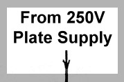
| Input From 250V Plate Supply |
| Output To BFO |
| Output To Other Circuits |
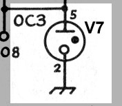
| Voltage Regulator Tube: A 0C3 gaseous regulator tube is used to provide a source of regulated voltage for the crystal calibrator, local oscillator, mixer screen grid, and BFO. Gaseous regulator tubes such as the 0C3 have the property that as long as the current through them is between about 5 mA and 40 mA the voltage across the tube is constant. For the 0C3, the voltage is 108 volts. The solid state equivalent of a gaseous regulator tube is the zener diode. You can click here for an 0C3 tube data sheet. |
 |
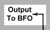
| Output To BFO: One of the circuits fed by the voltage regulator circuit is the beat frequency oscillator (BFO). The BFO is fed through the mode switch, so it is activated only in the CW mode. The BFO is very sensitive to plate voltage changes, and the voltage regulator circuit provides a source of regulated voltage to prevent such changes. |
 |
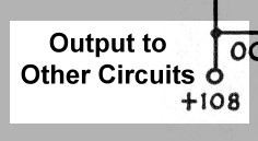
| Output To Other Circuits: There are other circuits in the 6x2 receiver that are sensitive to supply voltage changes, particularly the local oscillator and the mixer screen grid. Other circuits, such as the crystal calibrator, simply require a lower supply voltage, the the voltage regulator is a convenient source. |
 |
 Back to Dr.
Greg Latta's Electrical Engineering and Amateur Radio Pages
Back to Dr.
Greg Latta's Electrical Engineering and Amateur Radio Pages
 If you have any questions or
comments, you can send E-Mail to Dr. Greg Latta at
glatta@frostburg.edu
If you have any questions or
comments, you can send E-Mail to Dr. Greg Latta at
glatta@frostburg.edu