Click here for a higher resolution (larger) schematic.
Introduction:
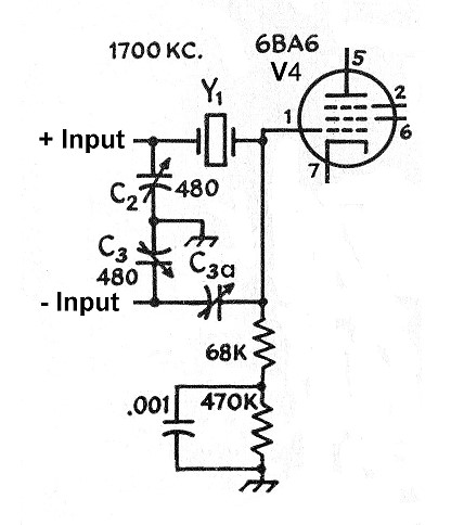
The output of the mixer is fed through a
crystal filter that utilizes a single quartz
crystal. Though a double crystal filter could have been used, a single
crystal filter provides higher selectivity and is more suitable for CW
reception. The two capacitors C2 and C3 are carefully balanced so that the
signal developed across them is equal but out of phase. Using a balanced input
to the filter allows the use of a null/phasing
capacitor to eliminate the bleed through caused by the crystal holder and
results in improved selectivity. The output of the filter is fed to the input
of the IF amplifier.
The crystal filter has a narrow enough bandwidth to give the 6x2 receiver single signal reception. This means that CW signals can only be tuned in on one side of zero beat, rather than both sides of zero beat. However, the selectivity is still wide enough to provide adequate SSB reception. If better SSB reception is desired, the null/phasing capacitor can be unplugged and a second 1700kHz quartz crystal can be plugged in in its place. Doing this, will, however, lessen the selectivity in the CW mode. The choice is up to the operator. I have found that a single crystal seems to work fine.
Crystal
Filter
Click On A Section of the Schematic
Below for Information on That Part of the Circuit:
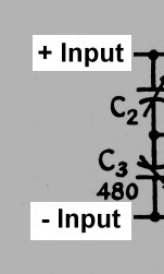
| Balanced Inputs |
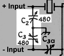
| Input Balancing Capacitors |
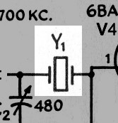
| Quartz Crystal |
| Null/Phasing Capacitor |
| Crystal Load Resistor |
| IF Amplifier Grid Resistor |
| Grid Resistor Bypass Capacitor |
| IF Amplifier |
| Balanced Inputs: The mixer tank circuit is floated above ground, and capacitors C2 and C3 are part of that resonant circuit. By grounding the junction of the two capacitors, two balanced inputs to the crystal filter are created. When one swings positive, the other swings negative. The two inputs are thus out of phase with respect to each other. |
 |
| Input Balancing Capacitors: Capacitors C2 and C3 are part of the mixer tank circuit. They are adjusted with a capacitance meter so that they have exactly the same value. Since the currents through them are the same, the voltages across each of them are identical. However, the phases are opposite, so when the top end of C2 swings positive, the bottom end of C3 swings negative. |
 |
| Null/Phasing Capacitor: Though the crystal bandwidth is very narrow, the plates that hold the crystal function as a capacitor, allowing unwanted signals to bleed through the crystal. This bleedthrough lessens the selectivity of the crystal filter. To get rid of the bleedthrough, we fight fire with fire: We connect a small capacitor with approximately the same capacitance as the crystal to the out of phase input to the filter, and intentionally allow some of the out of phase input to reach the output. When the capacitor is adjusted properly, this out of phase bleedthrough exactly cancels the signal bleeding through the crystal, restoring the selectivity of the filter. This is why the mixer is designed with a balanced output: we can use the out of phase output to cancel undesired signals leaking through the crystal. |
 |
| Crystal Load Resistor: The crystal operates best when it feeds a specific RF load resistance. Because of the grid resistor bypass capacitor, the bottom of the 68k resistor is grounded for RF, and the crystal therefore "sees" an impedance of 68kohms, not 538kohms (the series resistance of both resistors in series) as you might think. |
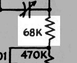 |
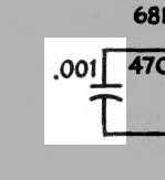
| IF Amplifier Grid Resistor: The cathode bias for the IF amplifier reaches the grid of the tube through the combined resistance of the 68k and 470k resistors. The presence of the 0.001 bypass capacitor does not affect this function. |
 |
| Grid Resistor Bypass Capacitor: A bypass capacitor is connected across the grid resistor to bypass any RF around the resistor. This short circuits the resistor for RF and guarantees that the RF load seen by the crystal is 68kohms, the resistance of the crystal load resistor. |
 |
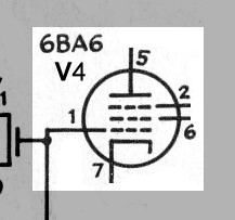
| IF Amplifier: The ultimate load of the crystal filter is the IF amplifier. The output of the crystal filter is coupled directly to the grid of the 6BA6 IF amplifier tube, where the signal is further amplified. |
 |
 Back to Dr.
Greg Latta's Electrical Engineering and Amateur Radio Pages
Back to Dr.
Greg Latta's Electrical Engineering and Amateur Radio Pages
 If you have any questions or
comments, you can send E-Mail to Dr. Greg Latta at
glatta@frostburg.edu
If you have any questions or
comments, you can send E-Mail to Dr. Greg Latta at
glatta@frostburg.edu