
Click here for a higher resolution (larger) schematic.
Introduction:
The mixer takes signals that have been filtered by the
input network and converts them
to an intermediate frequency of 1700 kHz by combining them with a signal from
the local oscillator.
This process is known as superheterodyning and is what gives the receiver its
name.
The two signals must be kept isolated from each other outside of the mixer.
Isolation is obtained by sending signals from the input network to the control
grid and the local oscillator signal to the cathode. This is known as cathode
injection.
In the mixer, the signals combine, producing two new signals at the sum and difference frequencies of the original signals. A resonant circuit in the output of the mixer selects only the 1700 kHz difference signal, rejecting any others. A capacitive voltage divider in the output is used to provide a balanced output with respect to ground to feed the crystal filter.
Mixer
Circuit
Click On A Section of the Schematic
Below for Information on That Part of the Circuit:

| Input Network: Signals from the input network enter the mixer at the control grid of the 6U8A pentode section. Because the input network has wide selectivity, it is possible for strong signals outside of the IF passband that cannot be heard in the receiver to pull or otherwise affect the mixer. This can be alleviated somewhat by detuning the input network. The 6x2 receiver has so much gain that any loss in gain caused by doing this can be made up by increasing the RF gain control, which is usually run at minimum. |
 |
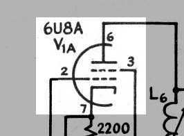
| Cathode Bias Resistor: The cathode bias resistor is very important in the mixer circuit. Current flowing through the resistor develops a voltage drop that makes the cathode positive with respect to ground. Since the grid of the tube is connected to ground through the input network, the grid is biased negative with respect to the cathode. Note that no bypass capacitor is connected across the cathode resistor as is typically done to prevent negative feedback. Rather, the cathode resistor also serves as the load for the local oscillator. The voltage developed across the cathode resistor by the local oscillator effectively varies the grid/cathode voltage, coupling the local oscillator output to the input of the tube, but without connecting it directly to the grid. If the local oscillator output were connected directly to the grid, the input network would short the local oscillator output to ground, ruining the injection. This method of coupling the local oscillator to the mixer is called cathode injection. |
 |
| Screen Bypass Capacitor: The screen bypass capacitor keeps the screen at ground potential for RF by shunting any RF to ground, while allowing the DC from the power supply to reach the screen. |
 |
| 6U8A Vacuum Tube: The 6U8A was originally designed for use as a mixer and local oscillator in television and FM receivers, and thus is ideal for this application. The triode is used as the local oscillator, and the pentode is used as the mixer. The two sections are internally shielded from each other. The "A" in the tube designation means that the tube has a controlled heater warm-up characteristic, which is not a consideration here. In this application either a 6U8 or 6U8A can be used. Click here for a 6U8A data sheet. I recently discovered that the popular 6GH8A tube can be used in this application as a direct plug in replacement. In fact, the 6GH8A may provide slightly better gain and improved resistance from pulling on strong signals. Click here for a 6GH8A data sheet. |
 |
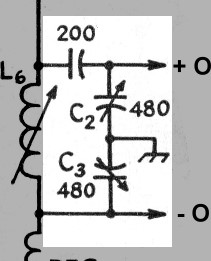
| Mixer Tank Coil: Coil L6 resonates with the capacitive voltage divider at 1700kHz. It is adjusted for maximum response at 1700kHz. The resonant circuit rejects all signals except those near 1700kHz. The response of this resonant circuit is fairly broad. Ultimate selectivity of the receiver is obtained from the crystal filter. |
 |
| Capacitive Voltage Divider: Three capacitors in series are used in the mixer tank circuit. The three capacitors have an effective capacitance of 109pf, which resonates with coil L6 at 1700kHz. Capacitors C2 and C3 are manually adjusted with an accurate capacitance meter to 480pf (plus or minus about 1%) each. This balance makes adjusting the crystal filter that follows easier. About 23% of the total voltage developed across the tank circuit appears across each of C2 and C3, and thus at each of the balanced outputs. This reduces the coupling between the mixer and the crystal filter and helps to maintain some of the selectivity of the mixer tank circuit. |
 |
| Plate RF Choke: Because of the balanced output of the mixer, both sides of mixer tank coil L6 must be above ground. The plate RF choke RFC1 allows DC to flow through while blocking the flow of any RF, keeping the mixer tank above ground. |
 |
| Plate Decoupling Capacitor: The plate decoupling capacitor shorts to ground any RF that may have made it through plate RF choke RFC1, preventing it from reaching the DC plate supply. |
 |
 Back to Dr.
Greg Latta's Electrical Engineering and Amateur Radio Pages
Back to Dr.
Greg Latta's Electrical Engineering and Amateur Radio Pages
 If you have any questions or
comments, you can send E-Mail to Dr. Greg Latta at
glatta@frostburg.edu
If you have any questions or
comments, you can send E-Mail to Dr. Greg Latta at
glatta@frostburg.edu


