Click here for a higher resolution (larger) schematic.
Introduction:
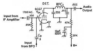
A grid leak detector is used in the 6x2 receiver. In a grid leak detector, the
tube functions as both a detector and as an amplifier. In such a detector, the
grid and cathode of the tube are used as a diode to rectify the signal from the
IF amplifier. The grid and cathode of the tube are in parallel with the
grid leak resistor. When the grid is positive,
the tube is forward biased and little current flows through the grid leak
resistor. When the grid is negative, the tube is reverse biased and no current
flows through the tube. Instead, the current flows through the grid leak
resistor. The result is a sequence of negative voltage pulses across the
resistor and the grid and cathode of tube.
The pulses are amplified by the tube and appear at the plate of the tube. The
amplitude of the pulses on the plate of the tube depends on the amplitude of
the RF coming from the IF amplifier. If the signal is amplitude modulated, the
size of the voltage pulses will vary with the amplitude of the RF, which
represents the original audio signal.
The voltage pulses are smoothed by the plate
filter capacitor, and the result is the demodulated audio signal. The
demodulated audio passes through the plate RF
choke, which removes any remaining RF. Finally, a
high cut capacitor shunts to ground the higher
audio frequencies, leaving only the more useful lower frequencies. The signal
then passes through a coupling capacitor to the
first audio amplifier.
For CW reception, a BFO signal at approximately
1701kHz is coupled to the grid. The signal mixes with the 1700kHz IF signal to
produce the equivalent of a 1kHz amplitude modulated RF signal. The resulting
amplitude modulated signal is then detected and demodulated as discussed above.
Detector
Click On A Section of the Schematic
Below for Information on That Part of the Circuit:

| Input Coupling Capacitor: The input coupling capacitor allows RF from the output of the IF amplifier to pass through to the detector, while blocking the IF amplifier plate voltage. |
 |
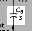
| BFO Coupling Capacitor: For CW reception, a signal at 1701kHz from the beat frequency oscillator (BFO) is also coupled to the grid of the detector. The BFO coupling capacitor allows this signal to pass through, while blocking the DC on the grid of the BFO. The value of the capacitor is also adjusted to limit the amount of the BFO signal getting through. Too much BFO signal would adversely affect the operation of the detector by producing too much bias on the tube. |
 |
| 6CG7 Vacuum Tube: The 6CG7 is a dual triode perfectly suited for operation as a detector and BFO. A general purpose triode, it is electrically equivalent to the popular 6SN7-GTB octal tube. One triode functions as the receiver detector, while the other section functions as the beat frequency oscillator. You can click on the following link for a 6CG7 tube data sheet. |
 |
| Plate RF Filter Capacitor: The voltage pulses on the grid of the tube ae amplifed and appear at the plate. The amplitude of the pulses on the plate of the tube depends on the amplitude of the RF coming from the IF amplifier. If the signal is amplitude modulated, the size of the voltage pulses will vary with the amplitude of the RF, which represents the original audio signal. The voltage pulses are smoothed by the plate filter capacitor, and the result is the demodulated audio signal. The demodulated audio passes through the plate RF choke, which removes any remaining RF. Finally, a high cut capacitor shunts to ground the higher audio frequencies, leaving only the more useful lower frequencies. |
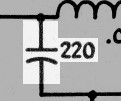 |
| Plate RF Choke: The plate RF choke allows the demodulated audio signal to pass through while blocking any remaining RF. The combination of the RF choke and plate RF filter capacitor effectively removes any RF, leaving only the demodulated audio signal at the output of the detector. |
 |
| Output Coupling Capacitor: The output of the detector passes through the output coupling capacitor to the first audio amplifier. The capacitor allows the audio to pass while blocking the DC on the plate of the detector. |
 |
 Back to Dr.
Greg Latta's Electrical Engineering and Amateur Radio Pages
Back to Dr.
Greg Latta's Electrical Engineering and Amateur Radio Pages
 If you have any questions or
comments, you can send E-Mail to Dr. Greg Latta at
glatta@frostburg.edu
If you have any questions or
comments, you can send E-Mail to Dr. Greg Latta at
glatta@frostburg.edu