Click here for a higher resolution (larger) schematic.
Introduction:
The first audio amplifier functions as a standard voltage amplifier to raise
the output of the detector to a level sufficient to drive the
audio power amplifier. To
guarantee enough gain, 1/2 of a 12AX7A was used. The other triode in the 12AX7A
was not used. (It could find use someday as an audio filter or part of an AGC
circuit.)
The maximum gain of the stage is approximately 35db. The actual gain is set by
the operator with the front panel AF Gain control. During initial testing and
use it was found that the AF Gain control was often near its minimum setting.
After an additional month or so of use, it was found that better settings of
the AF Control could be obtained by replacing the 12AX7A with the a 12AU7A. The
maximum gain with the 12AU7A is 22dB, and the 13dB decrease in gain resulted in
higher settings of the AF Gain control that were easier to control. No other
changes in the circuit were made other than replacing the 12AX7A with the
12AU7A.
First Audio
Amplifier
Click On A Section of the Schematic
Below for Information on That Part of the Circuit:

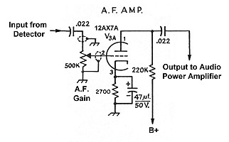
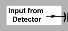
| Input from Detector: The input to the first audio amplifier comes from the detector stage. The detector output is too low to drive headphones or a speaker, so it must be amplified. |
 |
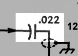
| Input Coupling Capacitor: The input coupling capacitor allows audio from the output of the detector to pass through, while blocking the DC voltage on the plate of the detector. |
 |
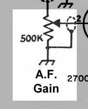
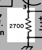
| A.F. Gain Control: The AF gain control serves three different functions: 1. After passing through the input coupling capacitor the output of the detector appears across the AF gain control. The control functions as an adjustable voltage divider, controlling the overall gain of the stage. It is more commonly known as the "Volume Control". 2. The control provides a load for the detector. 3. The AF gain control functions as a grid resistor, allowing the DC bias developed by the cathode bias resistor to reach the grid of the tube. |
 |
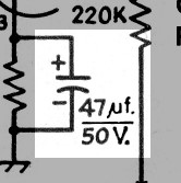
| Cathode Bias Resistor: Current flowing through the cathode bias resistor produces a voltage drop that is used to bias the tube. The cathode bias capacitor is connected across the resistor to smooth out any variations in the current and provide steady bias for the tube. |
 |
| Cathode Bias Capacitor: The cathode current flowing through the cathode bias resistor contains an AC component that must be shunted around the cathode bias resistor. The cathode bias capacitor shunts the AC component around the cathode bias resistor and smooths the voltage variations across the resistor, producing steady bias for the tube. |
 |
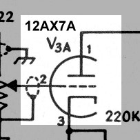
| 12AX7A Vacuum Tube: The 12AX7A tube is part of an entire series of dual triodes which also includes the 12AT7A, 12AU7A, 12AV7A, and 12AY7A. The primary difference between all of these is the gain of the tube. The 12AU7A has the lowest gain, and the 12AX7A has the highest gain. The 12AX7A is readily obtainable at music stores, since it is commonly used in guitar and instrument amplifiers. Not knowing how much gain would be needed, the 12AX7A was selected. As configured in the this circuit, the 12AX7A gives a gain of 35dB. Later, when it was found that the receiver had plenty of gain in other stages, the tube was changed to the 12AU7A, which lowered the gain by 13db to 22dB. This resulted in better settings of the AF gain control during typical operation. Only the tube needs to be changed. No other components need to be changed when making the substitution, The second triode is not used in the 6x2 receiver. You can click below for data sheets on the 12AX7A and 12AU7A: 12AX7A Tube Data Sheet 12AU7A Tube Data Sheet |
 |
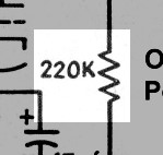
| Plate Load Resistor: The load resistor is connected between B+ and the plate of the tube. As the plate current increases, the voltage drop across the resistor increases, and the plate voltage decreases. The plate voltage thus varies with the plate current, but is out of phase with the plate current. The plate voltage variations pass through the output coupling capacitor to the audio power amplifier. |
 |
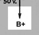
| B+: The first audio amplifier operates off of the B+ supply, which is nominally 250V in the 6x2 receiver. |
 |
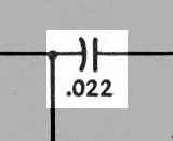
| Output Coupling Capacitor: The output coupling capacitor allows the output of the first audio amplifier to pass through to the audio power amplifier while blocking the DC plate voltage on the tube. |
 |
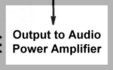
| Output to Audio Power Amplifier: The output of the first audio amplifier is not powerful enough to power a loudspeaker. To power a speaker, an audio power amplifier is needed, so the output of the first audio amplifier is sent to the input of the audio power amplifier. |
 |
 Back to Dr.
Greg Latta's Electrical Engineering and Amateur Radio Pages
Back to Dr.
Greg Latta's Electrical Engineering and Amateur Radio Pages
 If you have any questions or
comments, you can send E-Mail to Dr. Greg Latta at
glatta@frostburg.edu
If you have any questions or
comments, you can send E-Mail to Dr. Greg Latta at
glatta@frostburg.edu