
Click here for a higher resolution (larger) schematic.
Introduction:
The local oscillator is the heart of the receiver. It is the most critical
circuit in the entire receiver because any drift or instability in the local
oscillator will translate into drift and instability in the received signal.
Because of this, the local oscillator must be built with the greatest care and
the best components available. Silver mica capacitors must be used for all
fixed capacitors, and the main tuning coil must be of
the highest quality. The main tuning
capacitor must move smoothly with as little friction as possible.
Connections must be short, tight, and stiff to prevent microphonics. The local
oscillator is operated from a regulated voltage
source to eliminate changes caused by a fluctuations in the supply voltage.
In the 6x2 receiver, the local oscillator operates from approximately 5200kHz
to 5545kHz. When used with a 1700kHz IF, this means that the receiver can tune
3500kHz to 3845kHz or 6900kHz to 7245kHz. The receiver thus covers the bottom
345kHz of the 80m band and the bottom 245kHz of the 40m band with the same
local oscillator. The greatly simplifies construction and results in higher
performance. The frequency ranges covered by the receiver can be altered
slightly by changing the setting of bandset
capacitor C5.
By switching in trimmer capacitor C6, the local
oscillator fequency can be shifted down to 3300kHz to allow reception of WWV at
5000kHz .
Local Oscillator
Circuit
Click On A Section of the Schematic
Below for Information on That Part of the Circuit:

| Tickler Coil: The tickler coil L4 is wound on the same coil form as the main tuning coil L5 and provides inductive feedback to sustain oscillation. This is exactly the same method that used in a typical regenerative receiver. The amplifier signal in the plate circuit passes through the tickler coil and sets up a magnetic field that is picked up by the main tuning coil. This induces a signal in the main tuning coil that is in phase with the oscillation taking place there, providing positive feedback, sustaining the oscillation. This is very much like pushing on a swing to keep it moving. L4 consists of 7 turns of #24 enameled magnet wire spaced 1/32" apart wound on the same coil form as L5 and in the same direction as L5. The coil form for L4 and L5 is threaded 32 TPI to hold the turns in place to prevent them from moving and to provide stability. The separation between L4 and L5 is 1 1/2 turns. The lead for L5 that goes to ground and the lead of L4 that runs to the tickler bypass capacitor and plate dropping resistor are the leads at the gap between L4 and L5. |
 |
| Main Tuning Coil: Coil L5 resonates with the bandset capacitors and the main tuning capacitor at 5200kHz to 5500kHz. It consists of 17 turns of #24 magnet wire spaced 1/32" apart wound on a precision 3/4" plexiglass form that also holds L4. The coil form for L4 and L5 is threaded 32 TPI to hold the turns in place to prevent them from moving and to provide stability. The tickler coil L4 is wound 1 1/2 turns away from L5. The lead for L5 that goes to ground and the lead of L4 that runs to the tickler bypass capacitor and plate dropping resistor are the leads at the gap between L4 and L5. |

|
| Band Set Capacitors: Three capacitors in parallel resonate L5 to the desired frequency: 1. A 68pf fixed silver mica capacitor 2. C5, a 100pf variable capacitor 3. C7, the 35pf main tuning capacitor The fixed capacitor controls the range over which the receiver tunes. The 68pf capacitor was selected so the receiver would cover 300kHz on each band. However, the actual range covered depends on many things, including the actual inductance of L5 and the particular capacitor used for C7. With my receiver, the local oscillator wound up covering covering a range of 345kHz, somewhat more than originally intended. That is fine, because the receiver then covers more of the 80m and 40m phone bands. Bandset capacitor C5 controls the lowest frequency that the receiver will tune to. Capacitor C5 is adjusted so that the local oscillator runs at 5200kHz when main tuning capacitor C7 is fully meshed. The receiver will then tune either 3500kHz or 6900kHz when the dial pointer reads zero. With the particular components I used, my receiver covers 3500kHz to 3845kHz and 6900kHz to 7245kHz. |
 |
| Main Tuning Capacitor: Main tuning capacitor is a variable capacitor with a maximum capacitance of 35pf. When combined with the bandset capacitors in the local oscillator tank circuit, the main tuning capacitor will cover a range of approximately 300kHz. The actual range covered depends on the bandset capacitors and the main tuning coil. In my receiver, the range turned out to be 345kHz, rather than 300kHz. |
 |
| 6U8A Vacuum Tube: The 6U8A was originally designed for use as a mixer and local oscillator in television and FM receivers, and thus is ideal for this application. The triode is used as the local oscillator, and the pentode is used as the mixer. The two sections are internally shielded from each other. The "A" in the tube designation means that the tube has a controlled heater warm-up characteristic, which is not a consideration here. In this application either a 6U8 or 6U8A can be used. Click here for a 6U8A data sheet. I recently discovered that the popular 6GH8A tube can be used in this application as a direct plug in replacement. In fact, the 6GH8A may provide slightly better gain and improved resistance from pulling on strong signals. Click here for a 6GH8A data sheet. |
 |
| Regulated Plate Voltage: Changes in the plate voltage will alter the frequency of the local oscillator, so the plate voltage is obtained from a regulated souce. A 4700k dropping resistor is also used to further isolate the mixer from the power supply. |
 |
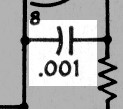
| Output To Mixer: The output of the local oscillator is coupled tightly to the cathode of the mixer through a 0.001uf capacitor. This is known as cathode injection, and helps to isolate the local oscillator from the other parts of the mixer. |
 |
| Output Waveform: This oscilloscope waveform was obtained by connecting an oscilloscope with a x10 oscilloscope probe to the cathode (pin 7) of the 6U8 mixer tube while the receiver was operating in the 40m band. The vertical scale is 50 mV/division and the horizontal scale is 0.05 us/division. Thus, the injection voltage at the cathode of the 6U8 is 5 div * 50 mV/div x 10 = 2500 mV peak-to-peak or 2.5 V peak-to-peak. The period is 3.8 div * 0.05 us/div = 0.19 us. This corresponds to a frequency of 5260 kHz. Note that the oscillator output is not a sine wave, but contains significant harmonic distortion, which is quite common. Pressing in the oscilloscope 20 MHz cutoff switch does not affect the waveform, indicating the distortion is 2nd and 3rd harmonic distortion. |
 Click on the image for a larger view. Click here for a super detailed view. |
 Back to Dr.
Greg Latta's Electrical Engineering and Amateur Radio Pages
Back to Dr.
Greg Latta's Electrical Engineering and Amateur Radio Pages
 If you have any questions or
comments, you can send E-Mail to Dr. Greg Latta at
glatta@frostburg.edu
If you have any questions or
comments, you can send E-Mail to Dr. Greg Latta at
glatta@frostburg.edu


