Click here for a higher resolution (larger) schematic.
Introduction:
The Johnson Ranger uses a pi-network for the final tank circuit to match the
high impedance of the final amplifier tube to the low impedance of the antenna.
The pi-network is ideally suited for this purpose because it allows for a wide
range of adjustment and attenuates undesirable higher harmonics that can cause
television interference (TVI).
One of the distinctive features of the Johnson Viking Ranger is
tank coil L11A. Most tank coils consist of a continuous
coil with taps, but in the Viking Ranger gaps are used between the various coil
sections to minimize losses in the final tank circuit.
Another distinctive feature of the Viking Ranger is the manner in which the
final tuning and antenna coupling are controlled. Rather than use a single
variable capacitor each for the final tuning (plate) and coupling (load)
capacitors, the designers at Johnson used a combination of variable
capacitors and fixed capacitors. The combination approach is preferable,
though more expensive, because it permits much finer adjustment of the final
tank circuit than is possible when only variable capacitors are used. After
using the Ranger for a while one can get spoiled by the ease with which the
Ranger can be tuned. The combination approach also permits the settings of the
final tank controls (Final, Auxiliary Coupling, and Coupling) to be easily
recorded so that the controls can be preset to their approximate positions when
changing bands. A slight touch up of the final tuning control to dip the final
amplifier current is all that is usually needed after changing bands.
Final Tank
Circuit
Click On A Section of the Schematic
Below for Information on That Part of the Circuit:
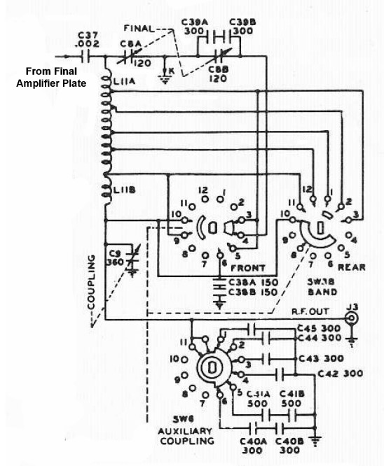
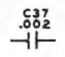
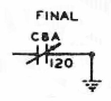
| Final (Plate) Tuning Capacitor: Variable capacitor C8A tunes the final tank circuit to resonance on the 20m - 10m bands. This control is normally adjusted for minimum final plate current. On the 40m, 80m, and 160m bands, extra capacitance is switched in by the front section of the bandswitch. Switching in extra fixed capacitance is preferable to using a single variable capacitor because it slows down the tuning rate on the higher frequency bands and makes the final tank circuit easier to adjust. |
 |
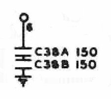
| Extra Final (Plate) Capacitors For 40m: Capacitors C38A and C38B are in series and form a 75pf capacitor. These capacitors are switched out by the front section of the band switch on all bands except 40m. On 40m they are switched in parallel with the final tuning capacitor C8A to provide the extra capacitance needed to tune 40m. Note: These capacitors are connected to C8A through the 10m section of the final tank coil L11A. The reactance of this section of the coil is so small on 40m that it is essentially a short circuit on 40m and has no effect on the connection. |
 |
| Extra Final (Plate) Tuning Capacitor For 160m and 80m: Capacitors C39A and C39B are in series and form a 150pf capacitor. This combination is then placed in parallel with variable capacitor C8B to form a variable capacitor with a maximum capacitance of 270pf. On 80m and 160m this combination is switched in parallel with the final tuning capacitor C8A by the front section of the band switch to provide the extra capacitance needed to tune 80m and 160m. Note: These capacitors are connected to C8A through the 10m section of the final tank coil L11A. The reactance of this section of the coil is so small on 80m and 160m that it is essentially a short circuit on these bands and has no effect on the connection. |
 |
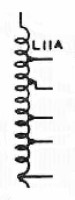
| 10m - 80m Tank Coil: Tank coil L11A is one of the distinctive features of the Johnson Viking Ranger. Most tank coils consist of a continuous coil with taps, but in the Viking Ranger gaps are used between the various coil sections to minimize losses in the final tank circuit. As the band switch is rotated clockwise from the 80m position to the 10m/11m position, sections are progressively shorted out by the front section of the bandswitch, lowering the inductance. |
 |
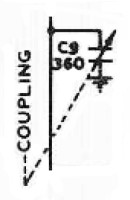
| Variable Coupling (Load) Capacitor: The coupling (load) capacitance of the final tank circuit is the total capacitance of coupling capacitor C9 and the auxiliary coupling capacitance in parallel. Switching in extra fixed capacitance is preferable to using a single variable capacitor because it permits the use of a smaller variable capacitor and slows down the tuning rate, making the final tank circuit easier to adjust and reset when changing bands. |
 |
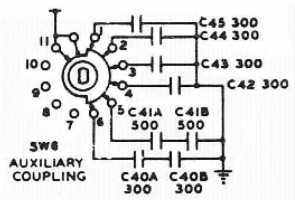
| Auxiliary Coupling (Load) Switch: The auxiliary coupling capacitance is in parallel with the variable coupling (load) capacitor. A seven position switch switches in/out extra capacitance as shown in the table below:
Note that the difference in capacitance between the switch settings is less than the maximum capacitance of the variable coupling (load) capacitor. By varying the settings of the coupling and auxiliary coupling controls, the coupling (load) capacitance can be precisely varied from a minimum of about 20pf to a maximum of 1960pf. Switching in extra fixed capacitance is preferable to using a single variable capacitor because it permits the use of a smaller variable capacitor and slows down the tuning rate, making the final tank circuit easier to adjust and reset when changing bands. |
 |
| Band Switch Front: The front section of the bandswitch switches in and out extra final (plate) tuning capacitance. On the 160m and 80m bands, an extra series/parallel combination of two fixed capacitors and a variable capacitor is switched in to provide the extra capacitance needed to tune these bands. On 40m, extra capacitance is needed, but less than on 160m and 80m. On 40m, a series combination of two fixed capacitors is switched in to provide the extra capacitance needed to tune 40m. On 20m and above no extra capacitance is needed, and none is switched in. On 11m, this section of the bandswitch also shorts out L11B, the extra 160m tank coil. |
 |
 Back to Dr.
Greg Latta's Electrical Engineering and Amateur Radio Pages
Back to Dr.
Greg Latta's Electrical Engineering and Amateur Radio Pages
 If you have any questions or
comments, you can send E-Mail to Dr. Greg Latta at
glatta@frostburg.edu
If you have any questions or
comments, you can send E-Mail to Dr. Greg Latta at
glatta@frostburg.edu