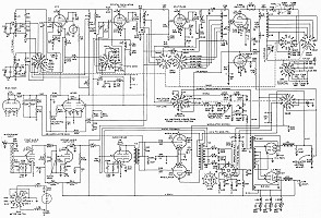
Click on the image for a larger view and access to
the individual circuits and schematic diagrams.
| Johnson Viking Ranger - Main Page and Exterior Photos | Alignment |
| Interior Photos of the Transmitter | Modifications |
| Restoration | Schematic Diagrams and Circuit Descriptions |
| Typical Operating Conditions | Manuals and Advertisements |
Important Safety Note: Working on or testing equipment such as the Viking Ranger is extremely dangerous since very high voltages are present when the equipment is turned on, and may even be present when the equipment is turned off and unplugged. If at all possible, do all work with the equipment off and unplugged and be sure that the capacitors are properly discharged before working on the equipment. The operator assumes all risk and liability in such matters! Do not work on this type of equipment unless you are experienced with working around very high voltages!
Introduction:
The Johnson Viking Ranger is a state of the art transmitter from the 1950s. It
uses frequency multiplication and is plate modulated, features which are
typical of AM phone/CW transmitters from that period.
The Ranger features a built in VFO, but is also capable of crystal controlled
operation. Circuits to suppress television interference (TVI) are used
extensively throughout the transmitter. The Ranger was built before solid state
rectifiers were perfected, so the power supply uses vacuum tube rectifiers
exclusively.
The Ranger is an advanced piece of equipment, but its operation can be
understood when it is broken down into its individual circuits. To learn how
each circuit works you can click on a link in the table below or you can click
on the portion of the schematic diagram that you are interested in. Either way
will take you to a separate page on that particular circuit.
Very High Resolution Schematic
Diagram:
A very high resolution copy of the entire transmitter schematic diagram is
available here:
Very High Resolution Schematic Diagram Of
The Johnson Viking Ranger
Right click on the link above and use the "Save Link As" or
"Save Target As" option to save the file on your hard drive. It is a
big file so I ask you to please avoid downloading it more than once if
possible.
This was obtained from a product brochure for the Johnson Viking Ranger, and is
the most detailed schematic I have been able to produce from that brochure. If
viewed with an image viewing program under magnification, or printed on a high
quality printer, it is possible to see exactly how the various rotary switches
in the Ranger function.
I suggest that you print this schematic out on an 8.5" x 11" piece of
paper and keep it next to you as you study the individual circuits. The
complete schematic diagram will keep you aware of how the circuits work
together as an entire group, while you study each circuit individually. You can
also crop the main schematic and print out individual circuits in high
resolution and excellent clarity.
Enjoy and 73,
Greg AA8V
| RF Circuits | Audio Circuits And Operate Switch |
Power Supply And Keyer Circuits |
| VFO | First Audio Amplifier | Bias/Keying Power Supply |
| Buffer/Crystal Oscillator | Second Audio Amplifier | Low B+ Power Supply |
| Multiplier | Audio Driver | High B+ Power Supply |
| Final Amplifier | Modulator | Timed Sequence Keying Circuit |
| Final Amplifier Tank Circuit | Operate
Switch AC Power/Control Section |
How
Timed Sequence Keying Works From Key Up To Key Down To Key Up |
| Clamper | Operate Switch - B+ Section | Meter Circuit |
| Accessory Socket |
Or
Click On Any
Part Of The Schematic Diagram Below For Information On That Part Of The
Circuit
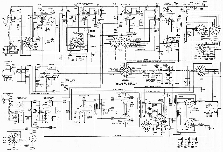
Click On Any Part Of The Schematic Diagram Above For
Information On That Part Of The Circuit
 Back to Dr. Greg Latta's
Electrical Engineering and Amateur Radio Pages
Back to Dr. Greg Latta's
Electrical Engineering and Amateur Radio Pages
 If you have any questions or
comments, you can send E-Mail to Dr. Greg Latta at
glatta@frostburg.edu
If you have any questions or
comments, you can send E-Mail to Dr. Greg Latta at
glatta@frostburg.edu