Click here for a higher resolution (larger) schematic.
How A Shunted Current Meter Works
A shunted current meter places a resistor in parallel with the main current
meter to shunt current around the meter. It allows the meter to measure
currents larger than the normal full scale rating of the meter. For instance,
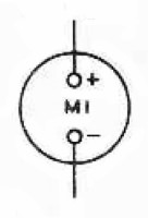
in the Johnson Ranger, the front meter is rated at 5mA full scale, yet the
meter can be used to read currents up to 200mA, as when it is used to read
plate or modulator current.
The shunt also allows the circuit to operate even when the meter is
disconnected from the circuit, since the shunt can carry the current in the
absence of the meter. By placing shunts in various circuits throughout the
transmitter, a single meter can be switched across the appropriate shunt to
measure the current in that particular circuit.
When the desired full scale current Ifs is flowing into
the system, the desired full scale current is split into two parts at point A.
Part of the current travels through the shunt (Ish) and
part flows through the meter (Im), as shown in the
diagram below:

Conservation of current requires that:
Thus, the shunt current is the desired full scale current less the full scale meter current:
In the case of the Ranger, Im=5 mA so:
Now, the meter movement has internal resistance, Rm. By Ohms law, this means that the full scale voltage Vfs across the meter terminals (points A and B) must be Im x Rm:
In the case of the Ranger:
Since the shunt and the meter are in parallel, the voltage across them is always the same so that:
By Ohm's law, the shunt current Ish times the shunt resistance Rsh must equal the voltage across the shunt Vfs so that:
By combining equations (2), (4), and (7) we obtain the equation for the shunt resistance:
In the case of the Ranger:
In the table below I have used equation (9) to calculate the various shunt resistances in the Ranger and compared the actual values to the calculated values:
| Shunt | Actual Shunt Resistance |
Circuit | Desired Full Scale Current |
Full Scale Shunt Current |
Calculated Shunt Resistance |
% Difference |
| SH1 | 3 ohms | Oscillator | 40mA | 35mA | 2.86 ohms | +5% |
| SH2 | 3 ohms | Buffer | 40mA | 35mA | 2.86 ohms | +5% |
| SH3 | 20 ohms | Grid | 10mA | 5mA | 20 ohms | 0% |
| SH4 | 0.51 ohms | Plate | 200mA | 195mA | 0.513 ohms | -0.6% |
| SH5 | 0.51 ohms | Modulator | 200mA | 195mA | 0.513 ohms | -0.6% |
As you can see, the actual shunt values are very close to the calculated values, especially when you consider the tolerances of the shunt resistors used.
Meter
Circuit
Click On A Section of the Schematic
Below for Information on That Part of the Circuit:
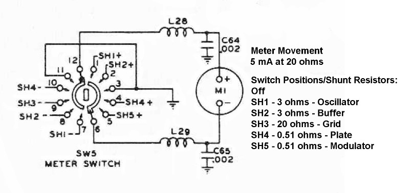
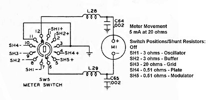
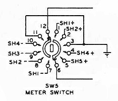
| Meter Switch |
| Shunt Resistors |
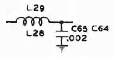
| L Network |
| Meter Movement |
| Meter Switch: Five different meter shunts are scattered throughout the Viking Ranger, as listed in the table below. The meter switch switches the appropriate shunt resistor across the meter. |
 |
| Shunt Resistors: Five circuits can be metered in the Viking Ranger. Each has a shunt resistor associated with it as listed in the table at right. The meter switch switches the appropriate shunt resistor across the meter. |
|
 Back to Dr.
Greg Latta's Electrical Engineering and Amateur Radio Pages
Back to Dr.
Greg Latta's Electrical Engineering and Amateur Radio Pages
 If you have any questions or
comments, you can send E-Mail to Dr. Greg Latta at
glatta@frostburg.edu
If you have any questions or
comments, you can send E-Mail to Dr. Greg Latta at
glatta@frostburg.edu