The Johnson Viking Ranger
by Greg Latta, AA8V
Oscillator Schematic and Circuit Description

Click here for a higher resolution (larger) schematic.
General Information:
The heart any transmitter is, of course, the VFO itself. It is here that the
ultimate stability of the transmitter is determined. The series tuned Colpitts
or Clapp oscillator used in the Viking Ranger is by and far the circuit of
choice for this application. The circuit features a large inductance to
capacitance (L/C) ratio which limits the current flowing in the main oscillator
coil. Limiting the current in the coil minimizes temperature changes in the
coil which lead to drift. The circuit also uses very small coupling between the
tuned circuit and the oscillator tube, which minimizes the effects that changes
in the tube (such as those that occur when the oscillator is keyed) have on the
frequency of the oscillator. This helps to minimize the chirp (frequency
change) that occurs when the oscillator is keyed, resulting in a much better
sounding CW signal.
The Ranger VFO operates over three frequency ranges. Two electrically
independent bandspread/bandset/coil combinations are selected by an internally
mounted VFO band switch that is linked to the front panel band switch. A third
VFO switch position switches in extra capacitance on the 11m band. The two
basic ranges covered are 1750kHz - 2000kHz and 7000kHz - 7425kHz. For
clarity, the VFO bandswitch connections and Operate switch connections are NOT
included in the schematic below. The schematic below assumes that the Band
Switch is in the 160m position and the Operate switch is in the VFO
position. Locations in the circuit that connect to the band switch or
operate switch are notated and marked with an "X".
VFO Circuit
- Series Tuned Colpitts (Clapp) Oscillator
Click On A Section of the Schematic
Below for Information on That Part of the Circuit:

Or click on one of the links below:
Series Tuned Colpitts (Clapp)
Oscillator:
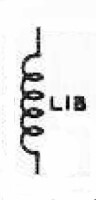
Main Coil:
The oscillator is the heart of the transmitter, but the oscillator coil is the
heart of the heart. The coil must be constructed to minimize any changes in
inductance due to temperature changes. Even the normal oscillator current in
the coil can cause sufficient heating to alter the inductance of the coil.
It is best to use an air core coil, since changes in the permeability of
ferromagnetic materials (powdered iron, etc.) with temperature will cause
changes in inductance. The wire should mounted so that no movement is possible.
In a Clapp oscillator, the tuning capacitance should be as small as
possible, which requires that the inductance to be relatively large.
The Viking Ranger use two electrically separate coils wound on the same ceramic
form. L1B is used used on the 160m and 80m bands, and L1A is used on the other
bands.
|
|
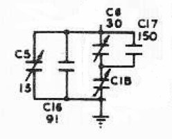
Tuning, Bandspread, Bandset, and Temperature Compensation Capacitors:
This tangle of capacitors is likely to scare anyone off, but in reality it
isn't as complicated as it looks. The entire arrangement is nothing more than
the equivalent of a temperature compensated variable capacitor with adjustable
maximum and minimum values. This arrangement was very common in the 1940s and
1950s, and allows the range of frequencies covered by the oscillator to be
easily adjusted.
The values shown in the schematic are the maximum values for the
variable capacitors C5 and C6. The actual values are determined when the
VFO is calibrated.
Variable capacitor C6 and fixed capacitor C17 are in parallel and form a
variable capacitor with a maximum value of 180pf. They are in series with main
tuning capacitor C1B, and the combination forms a variable capacitor that
changes value by an adjustable amount as C1B is varied from its minimum
to maximum position. The smallest change in value occurs when C6 is set to its
minimum value (plates fully unmeshed). The maximum change in value occurs when
C6 is set to its maximum value (plates fully meshed). Because the change or
spread in capacitance is controlled by C6, it is called the bandspread
capacitor.
Variable capacitor C5 and temperature compensating capacitor C16 are in
parallel and form a variable capacitor with a maximum value of 106pf. C16 is an
NP080 capacitor which means that its value decreases by 0.008% for each
1°C rise in temperature. This is to eliminate frequency drift by
offsetting other changes that are occurring throughout the oscillator as the
temperature changes. The value of C16 and its temperature coefficient were
determined largely by experiment when Johnson designed the Ranger transmitter.
The capacitance of C5 and C16, the bandset combination, is added
to the effective capacitance of the bandspread and main tuning capacitors and
allows the maximum capacitance of the entire combination to be adjusted. Since
C5 sets the maximum capacitance of the entire combination, it is called the
bandset capacitor.
Typically, the main tuning capacitor is fully opened and the bandset
capacitor adjusted to the highest frequency desired. The main tuning
capacitor is then fully meshed and the bandspread capacitor is adjusted
to the lowest frequency desired. This process is then repeated over and
over until the desired results are obtained. This process is called
"aligning" or "calibrating" the VFO.
|
|
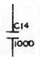
Grid Coupling Capacitor:
The effective tuning capacitor discussed above (the series/parallel
combination of the bandspread, main tuning, and bandset capacitors) is
connected in series with the grid coupling capacitor C14 and cathode
feedback capacitor C15. The effective capacitance of these three series
connected capacitors is then connected in parallel across the main
tuning coil, forming a parallel resonant circuit. The fact that the junction
between the effective tuning capacitor and the cathode feedback capacitor is
grounded does not affect this result.
The voltage developed across the main tuning coil is unequally divided across
these three capacitors in inverse proportion to their capacitance.
The HIGHER the capacitance, the SMALLER the voltage developed across it.
Most of the voltage appears across the effective tuning capacitor. The
remainder is split evenly between the grid coupling capacitor and the cathode
feedback capacitor.
The portion that appears across the grid coupling capacitor C14 is applied
through C18 and R2 across the grid and cathode of the 6AU6 tube, where it is
amplified. Because of the small value of C18 and the lower percentage of the
total tank voltage that appears across C14, changes in the tube caused by, for
example, keying the oscillator or changing the tube, have little effect on the
oscillator. It is this weak coupling between the resonant circuit and the
input of the tube that is an important characteristic of the Clapp
oscillator.
|
|
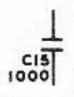
Cathode Feedback Capacitor:
The signal applied to the grid of the tube is amplified and part of the
amplified signal is taken from the screen grid (not the plate) of the
tube and is shunted to ground through the screen
bypass capacitor. This signal must get back to the cathode of the tube, but
it can't pass through the cathode RF choke, which
blocks any RF. Instead, it travels from ground back through the cathode
feedback capacitor C15 to the cathode of the tube. As it travels through the
feedback capacitor, it causes a small voltage to appear across the
capacitor. This voltage is in phase with the oscillation in the resonant
circuit and tends to assist the oscillation, restoring any energy that was
lost.
The voltage across a capacitor is in inverse proportion to the charge on
the capacitor. Because of the large size of the feedback capacitor, only a
small voltage is developed across the capacitor. This minimizes the
effect of the feedback on the oscillator, keeping the feedback to a minimum.
This keeps the size of the oscillation in the resonant circuit as small as
possible, minimizing any heating of the main tuning coil caused by the
oscillating current. It is this weak coupling between the resonant circuit
and the output of the tube (feedback) that is another important characteristic
of the Clapp oscillator.
|
|
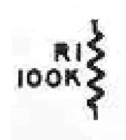
Grid Leak Resistor:
When the circuit is oscillating, some of the RF is rectified by the diode
action of the grid and cathode. This causes a voltage to develope across the
grid leak resistor (R1 and R36 in series), providing operating bias for the
tube. Resistor R1 also allows the grid-block keying voltage to reach the grid
of the tube while keeping the RF on the grid from flowing back to the keying
circuit.
|
|
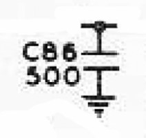
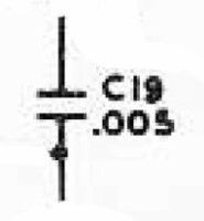
Grid Leak Capacitor:
The 500pf grid leak capacitor smooths out any voltage variations across the
grid leak resistor keeping the tube bias steady. The 500pf capacitor also
bypasses any RF leaking through the resistor to ground, preventing it from
getting to the keying circuit.
|
|
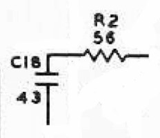
Grid Resistor And Capacitor:
Grid resistor R2 and capacitor C18 provide additional isolation between the
grid of the VFO tube and the tuned circuit. The extra isolation helps to
prevent changes in the tube operating conditions from affecting the frequency
of oscillation.
|
|
Keying Input:
Grid block keying is used in the Johnson Viking Ranger. While the key is up the
keying circuit applies a negative voltage through the grid leak resistor to the grid of the tube, shutting it
off.
When the key is pressed, the blocking voltage is removed and the circuit begins
oscillating.
|
|
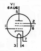
6AU6 Tube:
The 6AU6 is a 7-pin sharp cutoff pentode with high gain, and is perfect for use
as an oscillator. The small size and lower heater power allow it to be confined
inside of a cabinet without overheating.
You can click here for a 6AU6 Tube Data Sheet.
|
|
Cathode RF Choke:
Direct current must be allowed to flow to the tube cathode, but RF must be
blocked so that it flows through the cathode
feedback capacitor instead. This is done by connecting the cathode to
ground through an RF choke, which blocks RF but passes DC.
|

|
Screen Bypass Capacitor:
The screen grid of the tube serves as the plate of the oscillator in an
electron coupled oscillator. Some of the RF amplified by the tube must get back
to the resonant circuit to support oscillation. The screen bypass capacitor
allows the RF on the screen grid to pass through to ground while preventing the
screen DC supply from being short circuited.
The RF eventually flows through the cathode feedback
capacitor back to the cathode of the tube. When it flows through the
cathode feedback capacitor, it provides the
necessary feedback to keep the oscillator going.
|
|
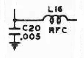
Plate RF Choke:
Direct current must reach the plate of the tube for proper operation, but the
RF appearing on the plate must not be permitted to reach the plate power
supply. The plate RF choke allows the DC to pass through, while preventing any
RF from getting through.
|
|
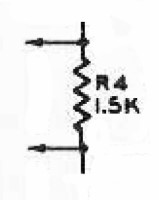
Output Control Resistor:
The output of most oscillators normally varies with frequency, and this is more
so in the Clapp oscillator circuit. When the VFO band switch is changed from
the 160m/80m position (1750kHz - 2000kHz) to the position for all of the other
bands (7000kHz - 7425kHz) the quadrupling in frequency causes the oscillator
output to drop considerably. To keep the output relatively constant, resistor
R4 drops the oscillator plate voltage in the 160/80m position. When the VFO
bandswitch is switched out of the 160m/80m position, contacts on the VFO band
switch short out resistor R4, raising the plate voltage on the
oscillator, increasing the output, and compensating for the change in
frequency. It is this attention to detail that makes the Ranger one of the best
transmitters of the 1950s.
|
|
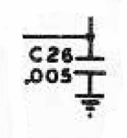
Plate Bypass Capacitor:
As extra insurance that any RF from the plate of the oscillator does not get
into the plate power supply, a capacitor is used to short circuit any RF that
might have leaked through the plate RF choke to
ground.
|
|
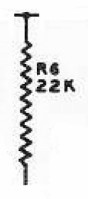
Output RF Load Resistor:
R6 is connected to the output of the oscillator and loads the oscillator for
RF, since the bottom end is grounded through the plate
bypass capacitor. Loading the oscillator lowers the overall Q of the
circuit and tends to equalize the output from one end of the tuning frequency
range to the other, keeping the oscillator output relatively constant.
|
|
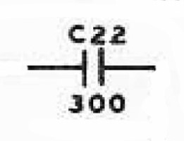
Plate Coupling Capacitor:
RF appearing at the plate must be fed to the next stage for amplification.
However, the DC plate voltage must not be allowed to pass through to the next
stage. The plate coupling capacitor allows the RF to pass through while
blocking the DC.
|
|
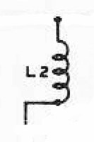
Filament and Cathode L-Networks:
There are many L-networks scattered throughout the Ranger transmitter. These
block RF more effectively than a bypass capacitor or RF choke alone, and are
used to prevent RF from going from one place to another.
The L-network is very effective because the capacitor shorts any undesired RF
to ground, while the RF choke blocks any RF that remains, and vice-versa. The
cathode network prevents any RF that may have escaped through the
cathode RF choke from getting through to the
Crystal/VFO switch, and the filament network prevents any RF on the filament
from getting away into the rest of the transmitter. The networks work either
way, regardless of which direction the RF is coming from, so they also prevent
stray RF from getting back to the cathode or filament from elsewhere in the
transmitter.
|
Cathode L-Network

Filament L-Network
|
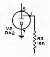
VR Tube and Dropping Resistor:
The frequency of the VFO is very sensitive to changes in the screen voltage,
which functions as the plate of the electron coupled oscillator. A gaseous
voltage regulator tube is used to keep the screen voltage constant, regardless
of voltage variations in the low B+ supply.
Resistor R3 is chosen so that the VR tube remains lit at all times. This
guarantees that the voltage across the VR tube (and thus the oscillator) is
constant. Resistor R3 is one of the weaknesses of the Ranger circuit. It
is inside the VFO cabinet and is not well ventilated, so it often burns out. If
you have never checked R3, remove the left side of the VFO cabinet to access it
and replace it if it has burned out. You may have to remove the entire VFO
cabinet to get to it. Use a 3W film resistor if you replace it. Do not use a
2W carbon resistor as was used originally. The carbon resistors are
unstable and subject to thermal runaway.
|
|
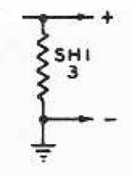
Metering Resistor:
When the "Crystal/VFO" switch is set to VFO or ZERO both the
oscillator (V2) and buffer (V3) cathode currents flow through the metering
resistor, creating a voltage drop across the resistor. (The connection to V3 is
not shown in the schematic diagram above.) When the front panel meter is set to
the "Osc" position this voltage drop is read and is used by the meter
to indicate oscillator/buffer cathode current.
When using crystal control, the cathode of V2, the VFO oscillator, is
disconnected, and the meter indicates only the crystal oscillator (V3) current.
|
|
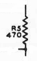
B+ Dropping Resistor:
Resistor R5 drops the low B+ voltage down to the value needed by the plate of
the VFO tube. In conjunction with the output control
resistor it determines how much the VFO output changes when the VFO band is
changed.
|
|
 Back to Dr.
Greg Latta's Electrical Engineering and Amateur Radio Pages
Back to Dr.
Greg Latta's Electrical Engineering and Amateur Radio Pages
Questions, Comments, and E-Mail
 If you have any questions or
comments, you can send E-Mail to Dr. Greg Latta at
glatta@frostburg.edu
If you have any questions or
comments, you can send E-Mail to Dr. Greg Latta at
glatta@frostburg.edu
Thanks for stopping by!