Antennas - An Introduction:
The antenna system is the most important part of any radio station. Since
antennas often have directional characteristics, many stations have several
antennas. At my station I have four antennas:
1. Butternut vertical
2. End fed wire
3. Zepp
4. "T" antenna
Which antenna I use depends on the band, the direction in which I wish to work
stations, and whether I am transmitting/receiving or receiving only.
If I wish to work DX or work stations in any direction on the 40m, 30m, and
20m, 15m, and 10m bands, I use the Butternut vertical.
For AM broadcast band listening and short wave listening I use the end fed wire
antenna.
On 80m and 60m I use the zepp antenna. I also use the zepp antenna on 40m if I
wish to work stations to the east or west. If I wish to work stations to the
north or south on 40m (e.g. Florida) then I use the Butternut vertical.
On 160m I use the zepp antenna reconfigured as a "T" antenna.
The station also features a radial system for
the Butternut vertical antenna as well as a fan
counterpoise system for use with the "T" antenna on 160m. Without
these "ground" systems the antennas will not work properly.
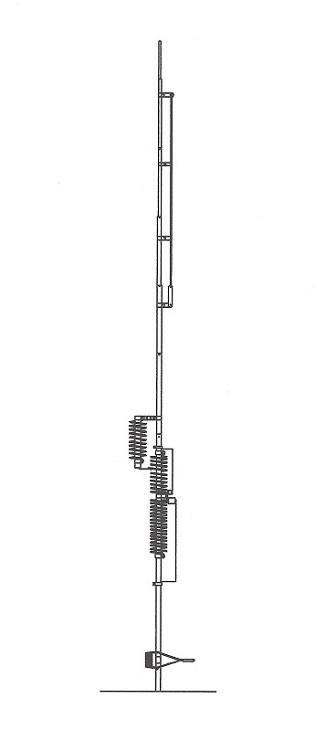 Butternut HF6V Vertical |
|
| Butternut HF6V Vertical: |
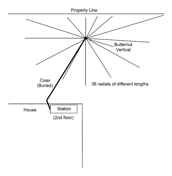
Butternut Vertical Radial System
Butternut Vertical Radial System:
All vertical antennas need a good radial system to work properly. The
"antenna" that we see above the ground is only half of the antenna
system. The other half of the antenna system is the radial network,
which radiates as much energy as the antenna itself. Simply connecting the
antenna ground lead to a ground rod will almost always result in poor
performance!. The other half of the antenna system will then either be
absent or so lossy that instead of radiating the energy it simply converts it
to heat. Likewise, on receive, a substantial amount of the received energy can
be lost, resulting in poor reception. If you decide to use a vertical antenna,
make the commitment to also provide a good radial system!
For my radial system, I made a circular piece of thick aluminum about 9"
in diameter (this could be square too) and then drilled and threaded 36 10-32
holes around the outside. This was then placed at the bottom of the vertical..
I then bought a 500 ft spool of #14 plastic coated stranded wire
("MTW" wire) and laid out 36 radials below the antenna. These are
fastened to the aluminum circle with stainless steel 10-32 screws. The
antenna isn't at the center of my lot. Instead, it is near one edge. As a
result, some of the radials are shorter (maybe only 10 ft long), and some of
them are longer (perhaps 40 ft long). The radials are simply laid on the ground
and then fastened in place with giant staples called landscape staples or
landscape anchoring pins. After a while, the grass grows up around the radials
and you can mow over them without any trouble.
Is this the perfect radial system? Probably not, but it seems to work. One
final point: Each year you should clean all of the connections with chemical
deoxidant and loosen and retighten all of the screws to break through any
corrosion and keep the connections sound. Make a commitment to not only install
the system but also to maintain the system.
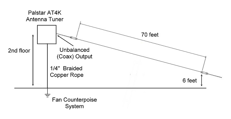
End Fed Wire:
The first antenna that I put up was a simple end fed wire. This is about 70
feet long and runs from the second floor window where the station is located
down to a large tree in the back yard. The far end of the antenna is about 6
feet above the ground. The antenna is made of #14 plastic coated solid copper
wire. Insulators are used at each end.
I originally used the antenna for both transmitting (with an antenna tuner) and
for receiving. Now, however, I only use the antenna for receiving. I normally
use this antenna with my Hallicrafters SX-96
receiver for broadcast band (AM) listening/DXng and for short wave listening. I
also use it with my Twinplex
regenerative receiver and with several other regenerative receivers and crystal
radios that I have in my collection. Though it is connected to one of the
coaxial inputs on the Palstar Antenna
Tuner, I usually bypass the tuner when using the antenna for
receiving. For transmitting, the antenna must be worked against some sort of
ground or counterpoise system that is connected
to the tuner.
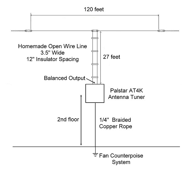
Zepp Antenna:
For the 80m, 60m, and 40m bands I use a classic multiband Zepp antenna. Another
name for such an antenna might be an non-resonant doublet or dipole. The beauty
of the zepp antenna is that it is balanced, and doesn't really need a ground
connection to operate. (Of course, the ground system is left connected anyway.)
The zepp is fed with homebuilt open wire line with a 3 1/2 wire spacing and a 1
ft spreader spacing.. The length of the antenna or feedline is not critical.
The antenna was as long as I could comfortably make it, 120 ft, and the
feedline length is whatever was needed for the connection, 27 ft. The antenna
essentially runs north and south.
The downside of the zepp antenna is that an antenna tuner with a balanced
output must be used to feed it. I use a
Palstar AT4K
antenna tuner. The Palstar tuners are superior to all other tuners in that they
do not place the balun at the output of the tuner, but rather at the
input of the tuner. The balun is always operated within its ratings and at
its optimum impedance, so there are essentially no balun losses in a Palstar
tuner. The entire tuner matching network then floats above ground to maintain
the proper balance. To feed unbalanced loads, such as coaxial cable, an end fed
wire, or a "T" antenna, one side of the network is simply grounded
through a heavy duty relay by pressing a button on the front panel.
"T" Antenna:
On 160m the impedance of a 120 ft zepp antenna is such that even the Palstar
antenna tuner cannot accomodate it. On 160m, the two ends of the feedline are
connected together to form a single wire which is then connected to the
unbalanced output of the tuner, and the tuner is placed in unbalanced mode. The
result is a "T" antenna which is then worked against ground or, in my
case, an extended radial/fan counterpoise
system. In this mode the feedline does not function as a feedline!
Instead, it radiates along with the rest of the antenna and the
ground/counterpoise system. It must be understood that in such a system
everything (including the "ground system") radiates RF and
contributes to the radiated signal. Since active parts of the antenna are right
at the back of the antenna tuner, there is a lot of RF in the shack, especially
when running high power. (But the lower frequency on 160m means that your body
won't absorb enough RF to cause any RF exposure problems.) Just don't touch
anything metal when transmitting, or you might feel the sting of an RF burn.
Fan Counterpoise System:
When I began operating on 160m with the "T"
antenna I found that a large ground current flowed into the AC house wiring
(neutral and ground wires) and also the house circulating hot water heating
system. This current caused interference with the phones, household appliances,
and heating thermostats.. On receive, the system picked up noise from all of
the devices in the house, raising the background noise on receive by an
unacceptable amount.
Since I couldn't disconnect the household ground system from the station
equipment, the solution was to provide someplace else where the current could
flow. I used a ground rod placed right below the station as a junction point
(though the rod itself serves no grounding function) where I could
connect several counterpoise wires. These are made of #14 plastic coated
stranded copper wire and were run as far as I could in a fan pattern over the
yard, as shown in the drawing. They are simply laid on top of the ground and
fastened to the ground with landscape staples or anchoring pins.
The ground rod is connected to the station antenna tuner on the second floor
with 1/4" braided copper rope (outrageously expensive if bought new!) that
a friend gave to me many years ago. It makes for a very low inductance
connection to the station.
After installing the fan counterpoise I found that the interference to the
appliances and phones in the house was greatly reduced, and that the background
noise on receive was also greatly reduced. The counterpoise was definitely
worth the time and money needed to install it.
Even with this counterpoise the station is still very hot with RF when
operating high power (more than 1kW output) on 160m , due to the proximity of
the antenna, which is only 27 ft away. I have to be careful not to touch any
metal in the station (like the bug or the antenna tuner roller) when
transmitting or I will get an RF burn. No system is perfect!
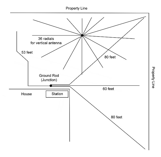
Radial and Counterpoise System Combined - "Ground"
System
Radial And Counterpoise Systems Combined - "Ground" System:
The figure above shows the complete radial and counterpoise system at AA8V.
Many would refer to this as the station "ground" system. Even though
the radials seem separate from the fan counterpoise, they are in fact connected
to each other. The shield of the coax that connects the antenna tuner to the
Butternut vertical also serves to connect the radials to the counterpoise. It
is a long connection, but on 160m it is short enough that ground current does
flow through the coax shield to the radial system. Thus, on 160m, the actual
counterpoise for the "T" antenna is the combined vertical
radial system and fan counterpoise system.
All of the wires are #14 gauge stranded plastic coated copper wire. None of the
wires are buried. Rather, the wires are fastened to the ground with landscape
staples or landscape anchoring pins. The grass eventually grows over the wires
and they become invisible.
 Back to Dr. Greg Latta's
Electrical Engineering and Amateur Radio Pages
Back to Dr. Greg Latta's
Electrical Engineering and Amateur Radio Pages
 If you have any questions or
comments, you can send E-Mail to Dr. Greg Latta at
glatta@frostburg.edu
If you have any questions or
comments, you can send E-Mail to Dr. Greg Latta at
glatta@frostburg.edu