Introduction and Historical Background:
After building several simpler receivers, I wanted to try my hand at a more
complicated, multi-band, multi-stage, receiver. Someday I wanted to build a
superhet, but I thought I should try building a really good regenerative
receiver first.
I searched through my old issues of QST and my old ARRL handbooks (I have both
back to the 1930s) and found many regenerative receivers to choose from, but
around the time that I was searching Lindsay Books came out with a book called
How to Build the
Twinplex Regenerative Receiver. The book told hold to build a two stage
regenerative receiver that used only one tube, just the sort of thing I was
looking for.
I purchased the book (and I highly
recommend it) and began work on the receiver. I had a brand new, black powder
coat chassis that I had gotten at a hamfest years ago that would serve as the
chassis. And I had a beautiful National Vernier that I could use as the
bandspread tuning capacitor. The layout would be completely different from that
in the book, but the circuit in the
book using a 6SL7
tube looked fine, and I decided to use it. I did make several important changes
in the receiver:
1. I decided to use a bandset/bandspread tuning arrangement rather than a
single tuning capacitor. This would allow stations to be separated more easily.
2. I decided to use AC on the filaments, rather than DC from batteries. This
would avoid the problem of buying or recharging batteries.
3. I decided to use a 6SN7 tube rather than a 6SL7 tube. (After building the
receiver I found that the 6SN7 worked better than the 6SL7).
The result of my efforts can be seen in these pages. The book does a great job of describing how to build the receiver, but I decided to write these pages on my version of the receiver and go a little more into the theory and operation of the receiver. I hope you find them useful.
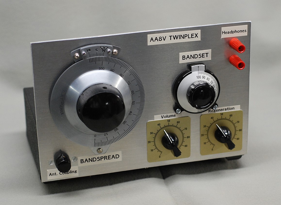
| Front Panel: This is a picture of the receiver front panel. I used a sheet of aluminum 3/32" thick, 9 1/2" high, and 6 1/4" tall for the front panel. Thinner aluminum can be used, but it won't be as stable. The thicker the front panel, the more stable the tuning, and the easier it will be to tune in stations. The large tuning control is the bandspread tuning, and the small control is the bandset tuning. With this arrangement, you use the bandset control to set the receiver to the approximate range you wish to tune, and then use the bandspread control for the final tuning. The antenna coupling capacitor is at the lower left, and the other two controls are the volume and regeneration controls. Headphones connect to the binding posts at the upper right. |
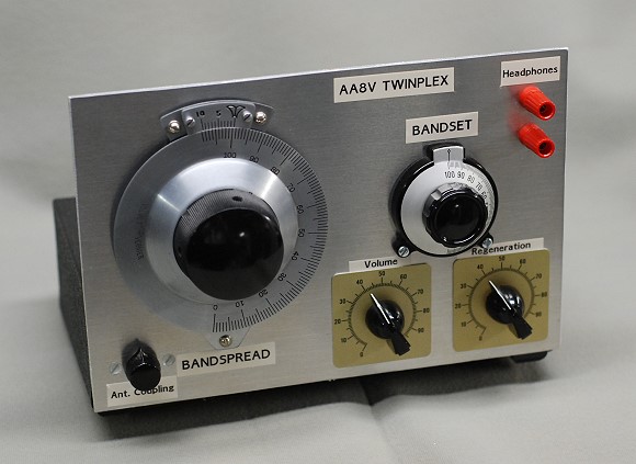 Click on the image for a larger view. Click here for a super detailed view. |
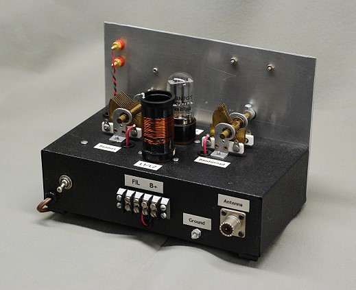
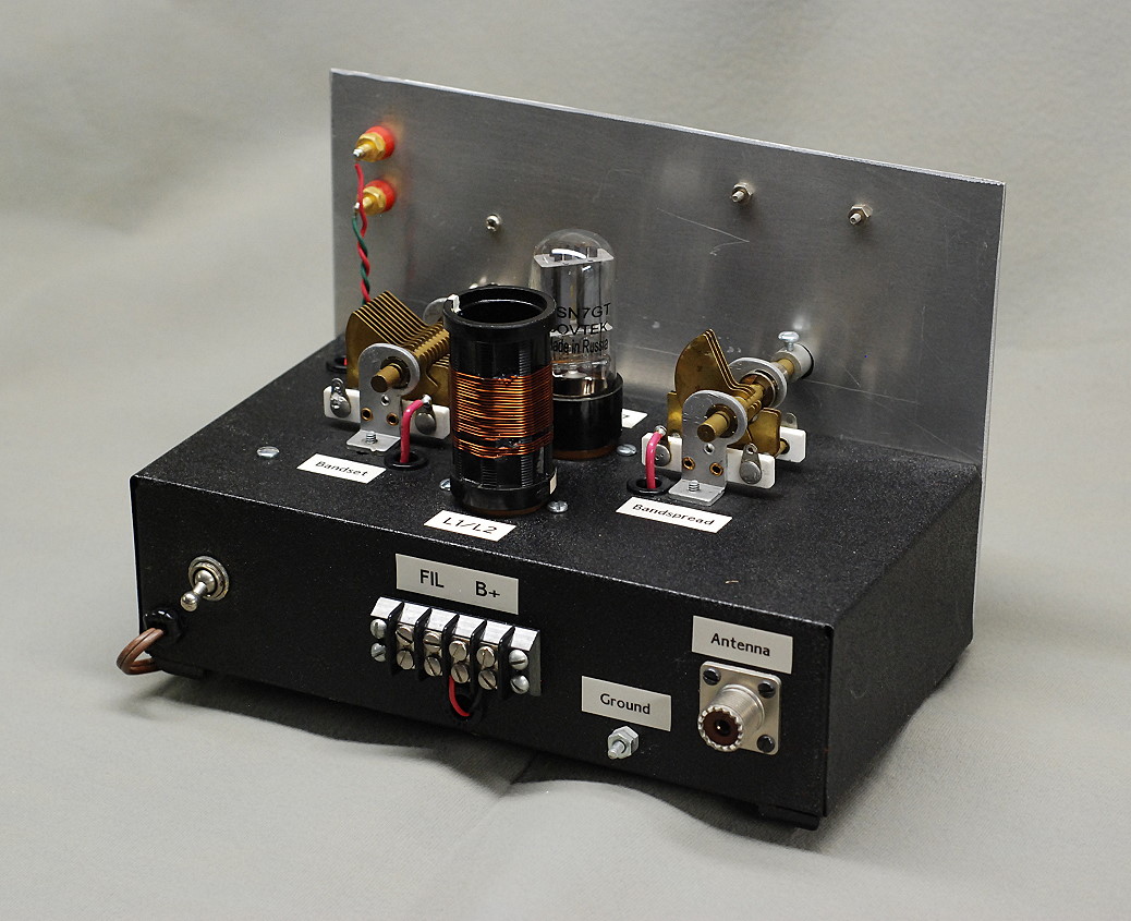
| Rear View #1: The receiver is built on a black sandpaper finished steel chassis 9 1/2" wide, 5" deep, and 2 1/2" tall that I found at a hamfest. The front panel is fastened to the chassis with the bottom of the front panel even with the bottom of the chassis. In this back view of the receiver, the filament power switch is visible on the back panel on the lower left. Note that the receiver still draws some current from the B+ battery even when the filament in off. Thus, it is important to disconnect the battery when the receiver is not in use. I later added a battery power switch to turn off the battery when not in use to avoid having to discconnect the battery. The 90 volt B+ battery is connected to the black terminal strip on the back panel. Originally, the filament transformer was external to the receiver, and was also connected to the terminal strip. Eventually, however, I decided to mount it inside the receiver, so the filament connections on the terminal strip are no longer used. The antenna is connected via the SO-239 connector on the right side of the back panel, and a ground wire is connected to the screw just to the left and below the antenna connector. |
Click on the image for a larger view. Click here for a super detailed view. |
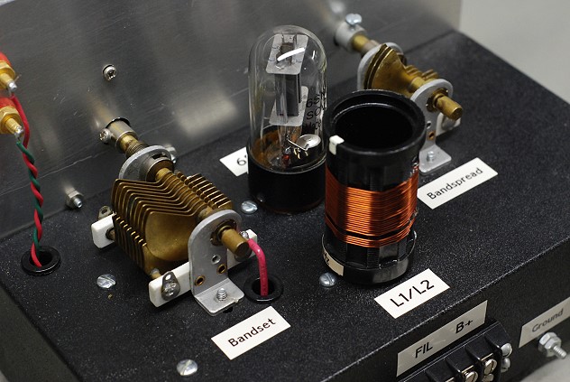
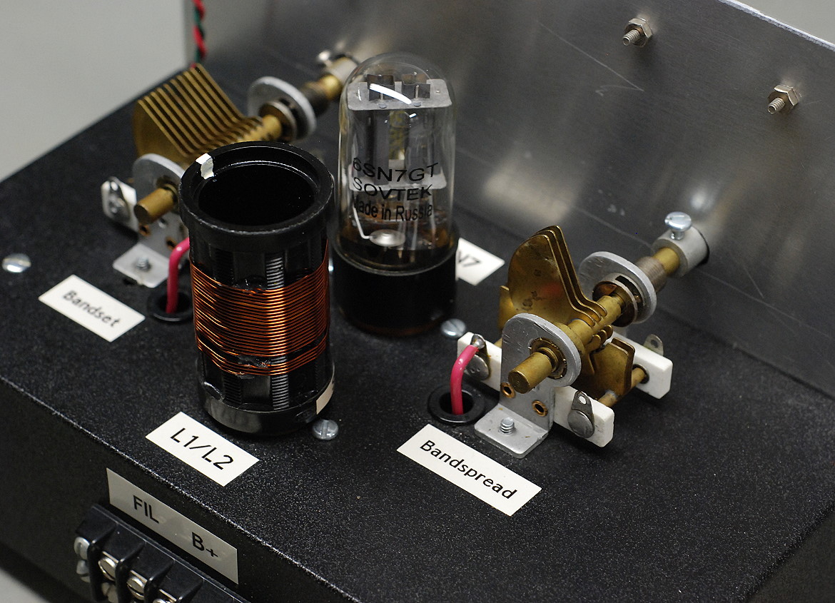
| Rear View #1 - Close Up: This is a close up of the top of the chassis. The bandset variable capacitor is on the left, while the smaller bandspread capacitor is visible to the right. The capacitors are bolted directly to the top of the chassis. In the center the plug in coil L1/L2 can be seen, with the 6SN7 tube in the back. The tickler winding L2 is at the bottom of the coil, and the larger main winding L1 is above the tickler winding. |
 Click on the image for a larger view. Click here for a super detailed view. |
| Rear View #2: In this alternate view of the rear of the receiver the power cord can be seen at lower left. Only the filament is run off of AC power. The B+ is still obtained from a battery. The headphone binding posts are visible on the back of the front panel at the upper left. The wires from the headphone binding posts pass though a grommet in the top of the chassis. After using the Twinplex for a while, I decided to add a switch for the battery and to mount an audio output transformer on the top of the chassis in the blank area above the antenna connector.. You can read about these and other modifications on the Twinplex Modifications page. |
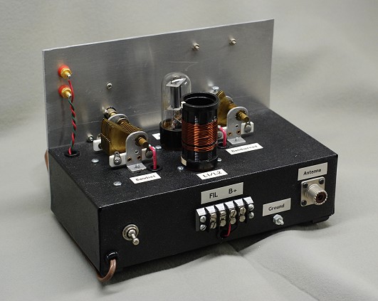 Click on the image for a larger view. Click here for a super detailed view. |
| Rear View #2 - Close Up: This close-up of the top of the chassis clearly shows the bandset variable capacitor. The bandset capacitor and bandspread capacitor both have unplated brass plates and were manufactured by Bud manufacturing. The bandset capacitor has a capacity of 10-140 pf, while the capacity of the bandspread capacitor is 5-38 pf. This means that the tuning of the bandspread control is about 3 1/2 times slower than that of the bandset control. |
 Click on the image for a larger view. Click here for a super detailed view. |
| Padder Capacitor Assembly: The ferrite rod coil used to tune the AM broadcast band requires a capacity of 328 pf to tune the bottom end of the band. The maximum capacity with both tuning capacitors meshed is (140 + 38) pf or 178 pf, which is not enough. To make up the difference, an additional 150 pf is placed in parallel across the bandset tuning capacitor as shown in the photo. With the padder connected, the receiver tunes from 560 kHz to 750 kHz. Without the padder, the receiver tunes from 730 kHz to 1550 kHz. |
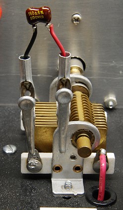 Click on the image for a larger view. Click here for a super detailed view. |
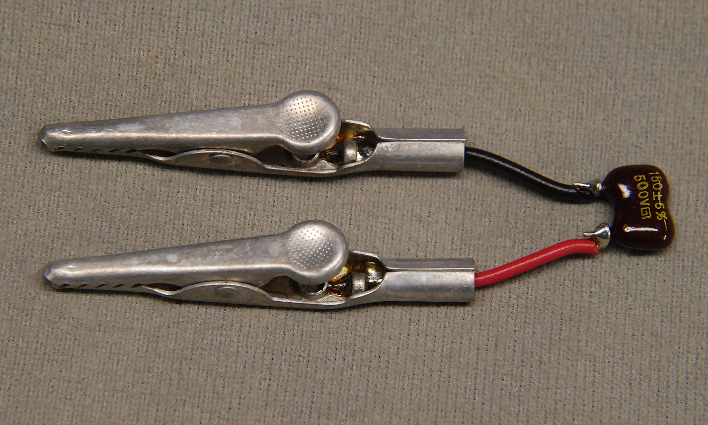
| Padder Capacitor Up Close: The padder capacitor is simply a 150 pf mica capacitor attached to a couple of alligator clips. The lead length should be kept as short as possible. This method is simpler and more effective than trying to use a switch to switch the padder in an out, since the extra wiring for the switch could affect the stability of the receiver. |
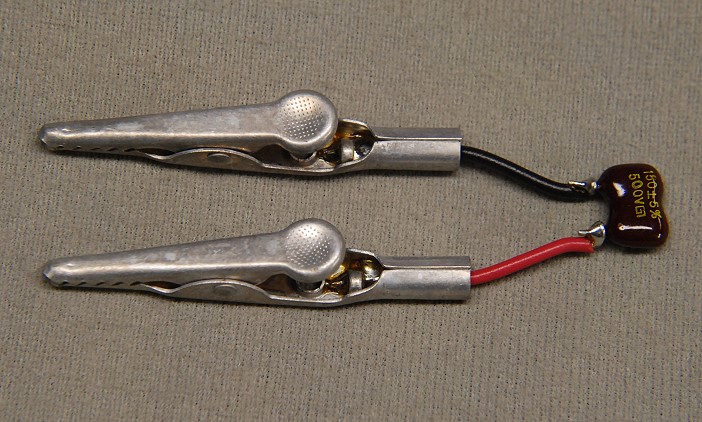 Click on the image for a larger view. Click here for a super detailed view. |
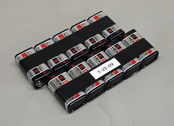
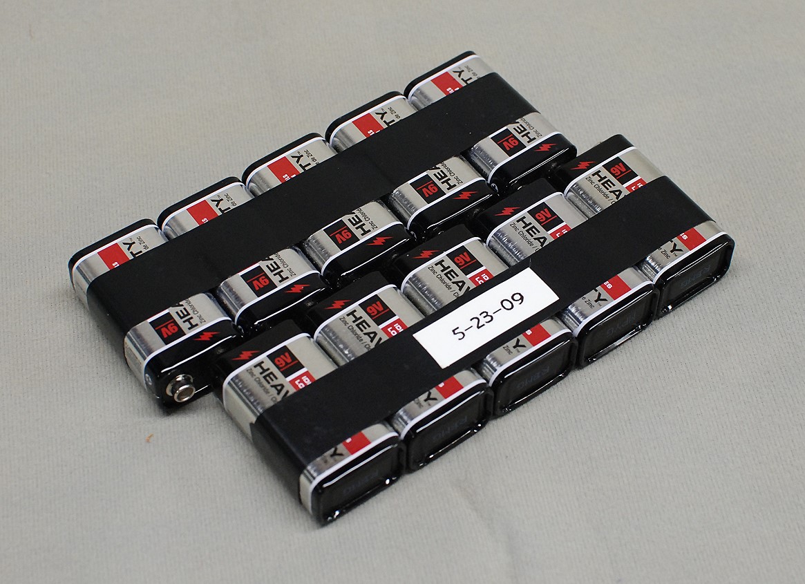
B+ Battery Assembly:
Use the cheapest batteries that you can get. The receiver current
draw is so low (about 3 or 4 mA) that using alkaline or other more expensive
batteries is a waste. I bought my batteries at Wal-Mart for 50 cents each,
making the total cost of the B+ battery $5.00. |
 Back to Dr.
Greg Latta's Electrical Engineering and Amateur Radio Pages
Back to Dr.
Greg Latta's Electrical Engineering and Amateur Radio Pages
 If you have any questions or
comments, you can send E-Mail to Dr. Greg Latta at
glatta@frostburg.edu
If you have any questions or
comments, you can send E-Mail to Dr. Greg Latta at
glatta@frostburg.edu