Click On A Section of the Schematic
Below for Information on That Part of the Circuit:
General Information:
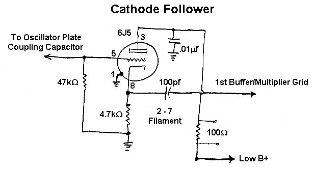
In the Wingfoot VFO Exciter the output of the oscillator is fed to a cathode
follower stage. The cathode follower isolates the oscillator from later stages
in the transmitter. The cathode follower is not keyed so it represents a
constant load on the oscillator, improving the keying of the transmitter.
A cathode follower is also known as a grounded plate amplifier, since the plate
is kept at ground potential for RF. Input is fed to the grid, and output is
taken from the cathode. The cathode follower has negative voltage gain:
the output voltage is less than the input voltage. However, it does exhibit
current and power gain. The cathode follower has a high input impedance
but a low output impedance.
Cathode Follower
Click On A Section of the Schematic
Below for Information on That Part of the Circuit:
| Grid Resistor |
| Cathode Resistor |
| 6J5 Tube |
| Plate Bypass Capacitor |
| Output Coupling Capacitor |
| Metering Resistor |
| Grid Resistor: The grid resistor serves as a load for the previous stage, and allows the grid bias developed across the cathode resistor to reach the grid of the tube. |
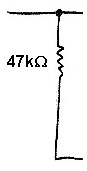 |
| Cathode Resistor: The cathode resistor creates cathode bias for the tube, and also serves as a load resistor. The output to the next stage is taken from across this resistor. |
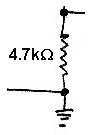 |
| 6J5 Tube: A 6J5 was used for the cathode follower in the Wingfoot VFO. The gain of the 6J5 is about the same as the popular 12AU7A miniature twin triode. You can click here for a 6J5 data sheet. |
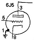 |
| Output Coupling Capacitor: The output of the cathode follower is taken from across the cathode resistor. The cathode resistor also generates the grid bias for the tube. To prevent the grid bias from flowing through to the next stage, and to prevent the grid bias of the following stage from appearing across the cathode resistor, a coupling capacitor is used. The capacitor allows RF to pass through, while blocking DC. |
 |
| Cathode Follower Metering Resistor: One of the unusual features of the Wingfoot VFO Exciter is the use of current metering resistors throughout the transmitter. One of these is included in the plate lead of the cathode follower. By connecting a voltmeter across the resistor and using Ohm's law, the cathode follower current can be determined. |
 |
 Back to Dr.
Greg Latta's Electrical Engineering and Amateur Radio Pages
Back to Dr.
Greg Latta's Electrical Engineering and Amateur Radio Pages
 If you have any questions or
comments, you can send E-Mail to Dr. Greg Latta at
glatta@frostburg.edu
If you have any questions or
comments, you can send E-Mail to Dr. Greg Latta at
glatta@frostburg.edu
