
| Introduction and
Front and Side View Photos |
Power
Supply, Interior, and Rear View Photos |
| Schematic Diagrams and Circuit
Descriptions |
Special
Features |
| Block Diagram |
Chassis Layout |
The Wingfoot VFO Exciter is very different from the typical homebrew (home made) transmitter of the 1950s. No expense was spared in its construction. The circuitry is unusually complex and the physical construction is unique. Below are listed some of the special features that make this transmitter so different from others of its era.
| Special Construction Features: | Special Circuitry Features: |
| Unique Chassis Construction | Series Tuned Colpitts (Clapp) Oscillator Circuit With 6AG7 Tube |
| Remote LC Circuit | Cathode Follower |
| Remote Power Supply | Differential (Timed Sequence) Grid Block Keying: |
| Remote T/R Switch and Meter Panel | Variable Regulated Screen Voltage On Final Amplifier: |
| Extensive Metering Capability For All Circuits |
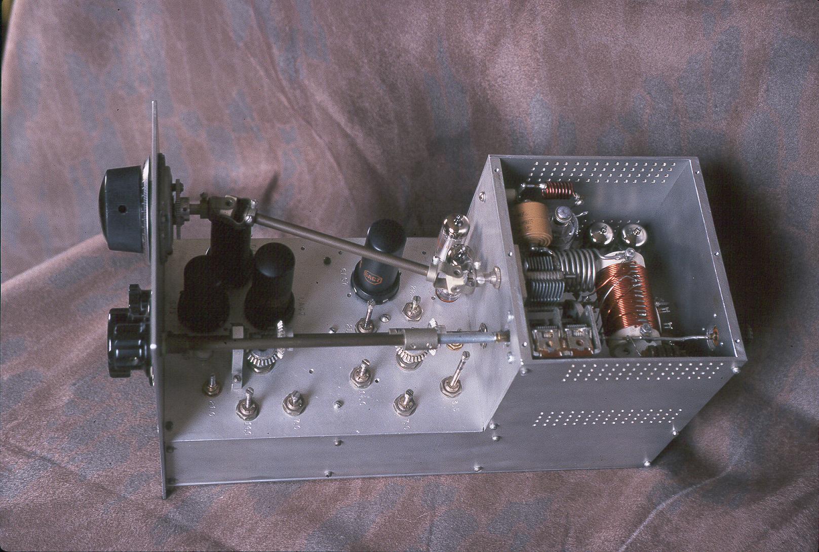
| Unique Chassis Construction: The Wingfoot VFO Exciter is built on a chassis made of heavy 3/32" and 1/4" aluminum plate. It is not made of bent or folded metal sheeting as is the usual case. The core of the chassis is made of four 1/4" aluminum "ribs". Two of these ribs, one just behind the front panel and another 1/3 the way back from the front panel, are underneath and cannot be seen. Two larger ribs form the front and back of the power amplifier cage. These can be seen at the right in the photo. The 1/4" ribs are drilled and tapped to take 4/40 screws and lockwashers that attach the 3/32" aluminum top, bottom, and side panels. In the photo at right the top of the power amplifier cage has been removed and you can see several of these tapped holes at the front and back of the cage. This method of construction is expensive and time consuming, but it results in a very strong and stiff chassis. It also allows for the temporary removal of the side and bottom plates for easy access while building or servicing the transmitter, a big plus. |
Click on the image for a larger view. Click here for a super detailed view. |
| Remote LC Circuit: The Wingfoot Exciter uses a Clapp, or series tuned Colpitts, oscillator. In this type of circuit, very high capacitances are shunted across the oscillator tube elements, minimizing frequency changes caused by changes in the tube. The high capacitance also permits the resonant circuit to be connected remotely to the tube via coaxial cables. The extra capacitance of the cables is small compared to the total capacitance, so the cables have little effect. Mounting the resonant circuit away from the main chassis minimizes drift caused by temperature changes. Changes in room temperature still affect the frequency of the oscillator, but these changes are much less than those that would have been caused by the tubes and other heat producing components on the main chassis. When the room temperature is reasonably constant, this gives the Wingfoot Oscillator/VFO a stability rivaling that of modern, synthesized, transceivers. The resonant circuit is housed on a chassis built of 3/8" aluminum which is very sturdy. A 5 to 1 planetary reduction drive slows down the tuning rate, making for easy tuning. |
 Click on the image for a larger view. Click here for a super detailed view. |
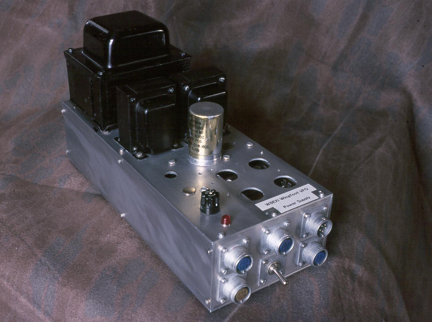
| Remote Power Supply: The power supply for the Wingfoot Exciter is on a separate chassis. This frees up desk space and allows for easier placement of the exciter. All power connections to the exciter and power supply are via shielded cables using Amphenol MS style connectors. These connectors are expensive but very secure and cannot be pulled off accidentally. |
 Click on the image for a larger view. Click here for a super detailed view. |
| Remote T/R Switch and Meter Panel: The remote control, at left in the photo, can be mounted at any location convenient to the operator. It offers three modes: Operate, Standby, and Spot. In Operate, all stages are active. In Standby, only filament voltages are activated, and the exciter plate supplies are disabled, which keeps heating in the power supply to a minimum. This feature in a transmitter is very rare. In Spot mode, the final amplifier is disabled, but all other stages are active, which allows the operator to hear the exciter signal in the station receiver. When placed in Operate or Standby mode, 120V AC is available from the exciter to activate a transmit/receive relay. In practice, the relay in the exciter is used to drive another larger relay which turns a set of four 120V AC outlets off and on. A Dow-Key antenna T/R relay is connected to one of these outlets. The Wingfoot 813 Amplifier power supply is connected to another of these outlets. Thus, in receive, both the exciter and amplifier plate power supplies are shut off, eliminating a lot of wasted heat. The meter panel, at right in the photo, connects to the exciter via shielded cable. It simultaneously monitors the final amplifier grid, screen, and plate currents on Weston type 301 milliammeters. Weston type 301 meters were among the best. Back in 1967, a single meter cost $14.40 from Allied Electronics, equivalent to about $85 today. Most transmitters have a single meter that is switched to read various functions, but in the Wingfoot Exciter the various currents in the final amplifier can be viewed at the same time. It is quite interesting to see how the various currents change and interact with each other as the transmitter is adjusted. In addition to the final amplifier currents, complete metering capability of all other circuits in the transmitter is also provided. |
 Click on the image for a larger view. Click here for a super detailed view. |
| Series Tuned Colpitts (Clapp) Oscillator With 6AG7 Tube: The heart of the Wingfoot VFO Exciter is, of course, the VFO itself. It is here that the ultimate stability and sound of the transmitter are determined. The Series Tuned Colpitts or Clapp oscillator is by and far the circuit of choice for this application. The circuit features a large inductance to capacitance (L/C) ratio which limits the current flowing in the main oscillator coil. Limiting the current in the coil minimizes temperature changes in the coil which lead to drift. The circuit also uses very small coupling between the tuned circuit and the oscillator tube, which minimizes the effects that changes in the tube (such as those that occur when the oscillator is keyed) have on the frequency of the oscillator. This helps to minimize the chirp (frequency change) that occurs when the oscillator is keyed, resulting in a much better sounding signal. Because of the large capacitances (1780pf) that are across the tube elements and the large inductance of the oscillator coil, it is possible to mount the LC circuit in a separate cabinet and connect it to the rest of the oscillator via shielded coaxial cables, marked "Grid Cable" and "Cathode Cable" in the schematic. (The cable shields are grounded and are not shown in the schematic.) Mounting the resonant circuit away from the main chassis minimizes drift caused by temperature changes. Changes in room temperature still affect the frequency of the oscillator, but these changes are much less than those that would have been caused by the tubes and other heat producing components on the main chassis. When the room temperature is reasonably constant, this oscillator/VFO has a stability rivaling that of modern, synthesized, transceivers. In an important 1950 article in QST magazine, "Crystal-Controlled Oscillators, A Review of Modern Crystals, Circuits and Tubes" (QST, March 1950, C. Vernon Chambers, W1JEQ) it was concluded, loud and clear, that of the four tubes tested in the article, the 6AG7, 6F6, 6V6GT, and 6L6, "the 6AG7 is by far the best from every standpoint." As a result of that article, virtually all crystal and self excited oscillator circuits in the ARRL handbook for the next 15 years featured or recommended the use of the 6AG7. The 6AG7 was thus used in the Wingfoot VFO Exciter as well. Click here for more information on the Series Tuned Colpitts/Clapp Oscillator. |
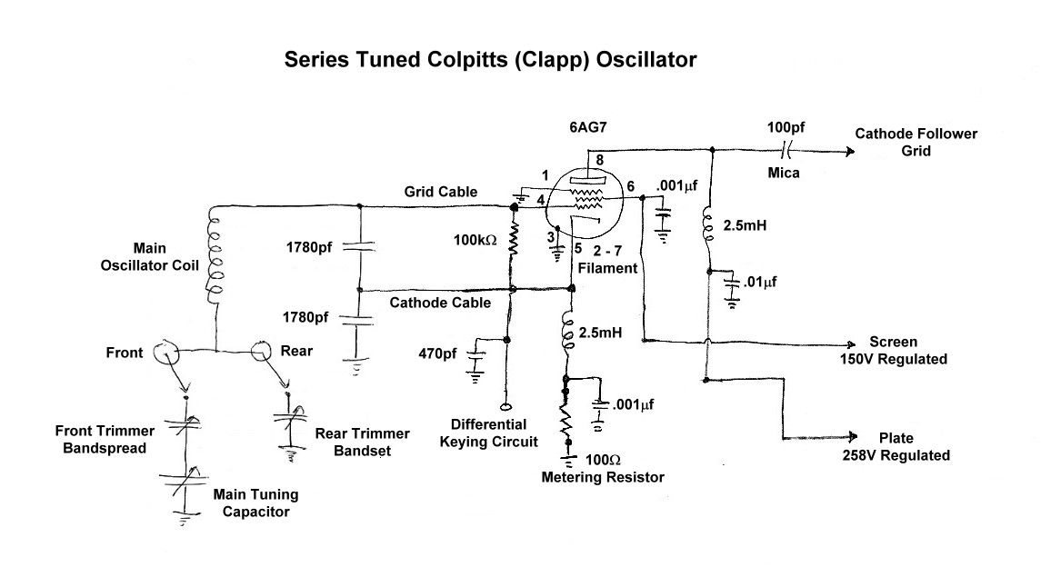 Click on the image for a much larger view. |
| Cathode Follower: In most transmitters the oscillator directly feeds a buffer or multiplier stage. However, studies in the 1950s showed that better isolation between the oscillator and the rest of the transmitter stages could be obtained by using a cathode follower immediately after the oscillator. The cathode follower has negative voltage gain (the output voltage is less than the input voltage), but the input to the cathode follower is virtually unaffected by changes in the load connected to the output. The cathode follower is not keyed, so the input to the cathode follower represents a constant load for the oscillator, preventing changes in later stages from affecting the frequency of the oscillator. The result is better oscillator stability and an improvement in the keying of the transmitter. Click here for more information on the cathode follower. |
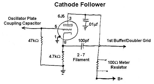 Click on the image for a much larger view. |
| Differential (Timed Sequence) Grid Block Keying: With separate receivers and transmitters most operators use the station receiver to monitor their keying by listening to the transmitter during transmission. If the oscillator is not keyed, a continuous "backwave" will usually be heard in the receiver between the individual dots and dashes. Some operators can ignore the backwave just fine, but most find that it is annoying or confusing and interferes with proper sending. The backwave can be eliminated by keying the oscillator along with other stages in the transmitter. However, the frequency of the oscillator will change slightly as the oscillator is turned on and off, resulting in what is known as "chirp" on the transmitted signal. In differential keying, the oscillator is not turned off and on at the same time as the other stages in the transmitter. Instead, when the key goes down, the oscillator is turned on first, before the rest of the stages. The later stages are then turned on, after the chirp in the oscillator has occurred. This prevents the chirp from being transmitted. When the key comes back up, the later stages are turned off first, followed by the oscillator. Again, the chirp occurs, but is not transmitted. The differential keying circuit in the Wingfoot Exciter is essentially the same as that used in the Johnson Viking Ranger transmitter, and some other Johnson transmitters. Johnson called it "Timed Sequence Keying". Click here for more information on differential/timed sequence keying. |
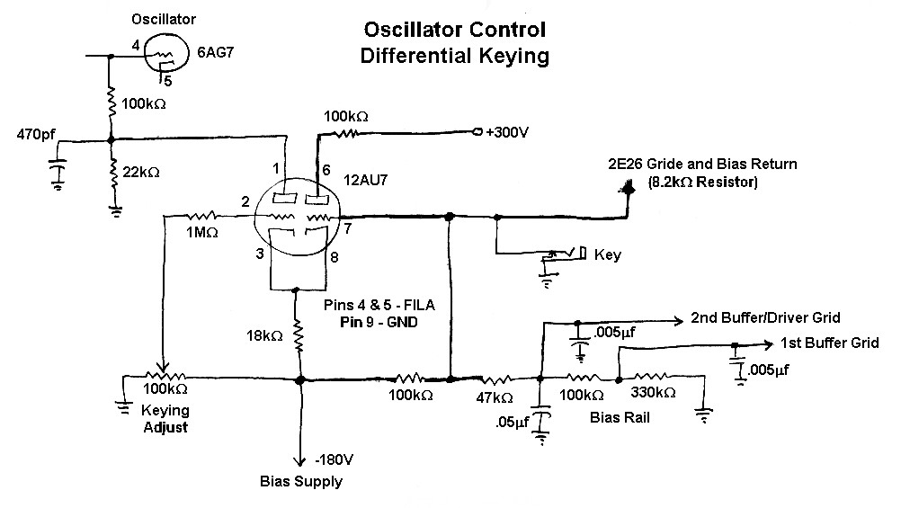 Click on the image for a much larger view. |
| Variable Regulated Screen Voltage On Final Amplifier: When a transmitter is used by itself, the transmitter is almost always run at full output. However, when the transmitter is used to drive an amplifier, some method of decreasing the output of the transmitter is often desirable. Most class C RF amplifiers use grid leak bias and get their screen voltage through a dropping resistor connected to the plate B+ supply. The screen dropping resistor is selected to provide proper screen voltage at full output. This is an excellent way to run an amplifier, but problems can occur when less than full output is desired. One way to get less output is to decrease the loading on the amplifier. However, this provides only a limited amount of control and can result in excessive screen current in screen grid tubes. If the drive to such an amplifier is decreased in an attempt to decrease the output, problems occur because the grid leak bias decreases. This causes the tube to overheat, even though it is producing less output! In the Wingfoot Exciter, full drive is kept on the output tube at all times, which keeps the grid leak bias at the proper value. During key up, blocking bias is applied to the tube to cut it off. Output power control is provided by varying the screen voltage on the final amplifier tube. The screen voltage to the final amplifier is provided through one section of a 12AU7 that functions as an adjustable voltage regulator. The screen voltage can be smoothly varied by changing the bias on the regulator tube using the output ("Screen") control. With this arrangement, the voltage on the screen can be set at about any desired value and varies less than 11% between key up and key down. This prevents output spikes during keying, common with other RF amplifiers, that give the keying a harsh sound. Using the output ("Screen") control, the output of the Wingfoot Exciter can be smoothly varied from less than 3 watts up to the full output of 27 watts. The clamp tube protects the final amplifier tube in case drive is lost while the key is down. The grid of the clamper tube is connected to the bias on the final amplifier tube. The presence of either grid-block or operating bias cuts off the clamper tube, and it has no effect. However, if drive is lost during key-down, the clamper tube turns on, removing the positive voltage at the top of the output control. This turns down the screen voltage regulator, lowering the screen voltage. This lowers the final amplifier plate current, protecting the tube. Click here for more information on the screen regulator and clamp tube. |
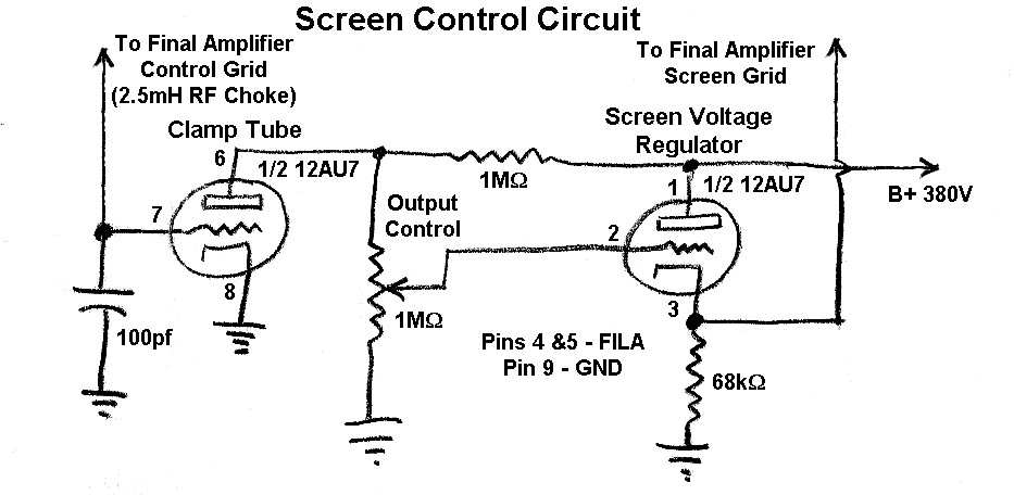 Click on the image for a much larger view. |
| Extensive Metering Capability Of All Circuits: Most tube transmitters have a single meter and a switch to provide metering of the final amplifier grid and plate current. In some cases, other circuits can be metered as well, but the limit is usually five different circuits. The Wingfoot Exciter avoids the need for a switch by having three separate meters for the final amplifier grid, plate, and screen currents.. This makes it possible to monitor the operation of the final amplifier with a single glance at the meters. However, additional metering of virtually all other circuits in the transmitter is possible due to the bank of metering resistors built into the transmitter. A total of seventeen 100 ohm resistors (11 ohms for the power amplifier grid) are placed in series with virtually every current drawing circuit in the transmitter. For example, the oscillator plate, screen, and cathode each have resistors in series with them so that the oscillator plate, screen, and cathode current can be separately monitored. The relatively low value of the resistors does not alter the operation of the circuits, but allows one to connect a voltmeter across the resistor and then use Ohm's Law to compute the current through the resistor. I have never seen such a metering circuit in any other transmitter. Such metering capability as absolutely unique to the Wingfoot VFO Exciter. I found this metering capability extremely useful when repairing and restoring the transmitter. At right, the upper picture is the schematic diagram of the metering circuit, and the lower photo is a picture of the metering resistors. Nine of the resistors (brown-black-brown) are visible at the right in the picture, and eight more are under the brightly colored resistors in the center of the photo. |
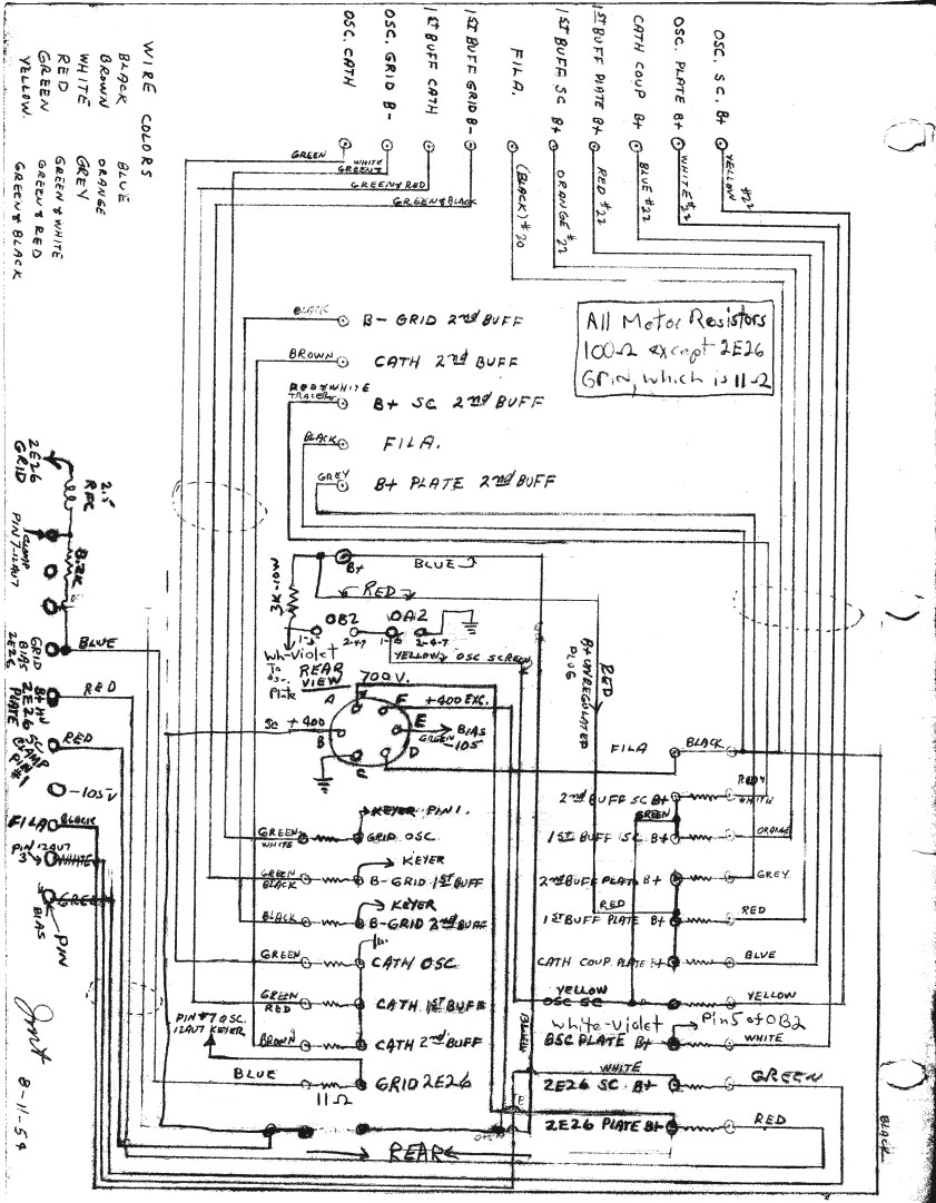 Click on the image for a much larger view.  Click on the image for a larger view. |
 Back to Dr. Greg Latta's
Electrical Engineering and Amateur Radio Pages
Back to Dr. Greg Latta's
Electrical Engineering and Amateur Radio Pages
 If you have any questions or
comments, you can send E-Mail to Dr. Greg Latta at
glatta@frostburg.edu
If you have any questions or
comments, you can send E-Mail to Dr. Greg Latta at
glatta@frostburg.edu