The W8EXI Wingfoot VFO Exciter
How The Differential/Timed Sequence Keying Circuit Works:
This page discusses how the differential/timed sequence keying
circuit works from key up, to key down, and back to key up. For a detailed
discussion of the individual components in the circuit and what they do see the
following link:
Differential/Timed Sequence Keying
Schematic Diagram and Circuit Description
General Comment:
When I first encountered the circuit below, I was, quite frankly, thoroughly
confused. It is an uncommon circuit and the operation is confused by the fact
that it uses two power supplies, one positive ground (the bias supply), and one
negative ground (the plate supply). However, after making voltage measurements
and spending a good deal of time studying the circuit, I now understand exactly
how it works. This page is my way of passing that information on to you.
Main Purpose of Differential (Timed Sequence)
Keying:
The main purpose of differential keying is to prevent chirp caused by keying
the oscillator from being transmitted. This is accomplished by doing two
things:
1. The oscillator is grid-block keyed using the minimum voltage necessary to
reliably turn off the oscillator. When the blocking voltage is removed, the
oscillator quickly turns on and quickly stabilizes. This minimizes the time it
takes for any frequency changes (i.e. "chirp)" to occur. When the
blocking voltage is restored, the oscillator turns off slowly, since it is
barely cut off. This delays the time it takes for the chirp to occur.
2. Other circuits in the transmitter must also be keyed in proper
sequence. They must be turned on a short time after the oscillator has had
a chance to stabilize, and they must be turned off as quickly as possible,
before the oscillator has a chance to turn off.
If the previous two rules are followed, any chirp created by the oscillator
will not be transmitted, and the result is a clean, chirp free signal.
What the Differential Keying Circuit Must
Do:
The differential keying circuit must do four things:
1. The differential keying circuit must provide an adjustable cutoff
voltage for the oscillator. The exact cutoff voltage needed for the best
keying depends on many things, such as the type of oscillator tube used, the
brand of oscillator tube used, the age of the oscillator tube, etc. By making
the cutoff voltage adjustable, it can then be precisely adjusted by listening
to the keying for best performance. When set to the proper value, the
oscillator will turn on quickly, yet turn off slowly.
2. The differential keying circuit must allow the adjustable cutoff voltage
to be turned off and on instantaneously by the key, while also allowing the key
to control the other circuits in the transmitter.
3. When the key is closed, the oscillator must turn on fully before at least
one other circuit down the signal chain also turns on.
4. When the key is opened, the oscillator must remain on long enough for at
least one other circuit down the signal chain to turn off before the
oscillator.
The above requirements might seem difficult to implement, especially using
1950s technology, but the circuit below does the job. The basic circuit was
first published in an article in the September Issue of QST Magazine titled
"De Luxe Keying Without Relays" by T.H. Puckett, W2JXM. It was used
by Jim Trutko, W8EXI, when he built the Wingfoot VFO Exciter and it was also
used by the E.F. Johnson Company in several of their transmitters, such as
their Viking Ranger.
How The
Differential/Timed Sequence Keying Circuit Works:
Scroll down for a complete description of how the differential
keying circuit works.
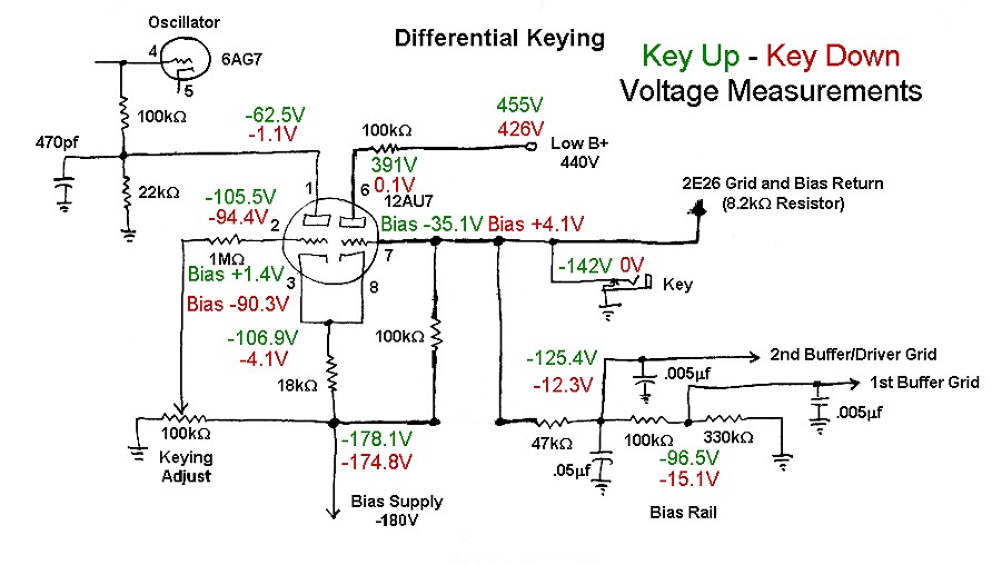
Circuit voltages during key up and key down.
Green indicates key up. Red
indicates key down.
All voltages are with respect to ground. Bias voltages are with respect to the
tube cathodes.
To understand how the circuit works, it is best to
consider the following four situations:
It is assumed that the
keying adjust
potentiometer has been set
for the best keying by listening to the transmitter in a receiver.
Key Up:
When the key is up, three things are in place:
1. The left triode is turned on. The negative bias produced by the
cathode bias
resistor and the positive bias from the
keying adjust
potentiometer combine to place +1.4V of bias on the left triode. The
current flowing in the left triode passes through the 22kohm
cutoff bias
resistor producing a voltage drop of 62.5V across the resistor. This passes
through the 100kohm grid
leak resistor and cuts off the oscillator.
2. The bias produced across the
cathode bias
resistor also passes through the 100kohm
2nd grid resistor
and combines with the positive bias from the
bias rail to place -35.1V
of bias on the right triode grid, cutting off the right triode.
3. Negative bias from the bias supply passes through the 100kohm
2nd grid resistor
to the key, the
bias rail, and the
2E26 grid. The capacitors
in the bias rail are charged up and the final amplifier and 1st and 2nd buffers
are all cut off.
Key Closes:
When the key closes, three things happen:
1. The negative voltage on the grid of the right triode is shorted to ground.
This places +4.1V of bias on the right triode grid, turning on the right
triode. The current in the right triode flows through the
cathode bias
resistor greatly increasing the voltage across the resistor. This extra
cathode bias voltage passes through the
keying adjust
potentiometer and 1st grid resistor to
the grid of the first triode, cutting it off. This removes the cutoff bias from
the oscillator. The oscillator turns on quickly because the minimum blocking
bias was used to turn it off. All of this happens instantaneously, without
delay. This satisfies the requirement that differential keying circuit must
allow the adjustable cutoff voltage to be turned off and on instantaneously by
the key, while also allowing the key to control the other circuits in the
transmitter.
2. The negative voltage on the final amplifier is immediately removed, turning
it on.
3. The negative voltage on the 47kohm resistor feeding the bias rail is
removed. This causes the 0.05uf capacitor to begin discharging. After about
2ms, when the capacitor is sufficiently discharged, the blocking bias is
removed from the 1st and 2nd buffers, and they turn on, after the oscillator
has turned on. This satisfies the requirement that the oscillator must turn
on fully before at least one other circuit down the signal chain also turns
on.
Key down:
When the key is down, three things are in place:
1. The right triode is turned on because the grid is grounded through the
key. The current through the
right triode produces a large voltage across the
cathode bias
resistor.
2. The left triode is turned off because of the large negative bias from the
cathode bias
resistor. There is no cutoff bias on the oscillator, and the oscillator is
on.
3. The final amplifier, 1st buffer, and 2nd buffer grid leak resistors are all
grounded through the key and
47kohm resistor in the bias
rail, turning all of them on.
Key Opens:
When the key opens, three things happen:
1. The negative voltage on the final amplifier is immediately restored, turning
it off.
2. The negative voltage on the grid of the right triode is restored. This
places -35.1V of bias on the right triode grid, turning off the right triode.
The drop in current flowing through the
cathode bias
resistor greatly reduces the voltage across the resistor. This reduction in
cathode bias voltage passes through the
keying adjust
potentiometer and 1st grid resistor to
the grid of the first triode, turning it on. This current in the triode passes
through the 22kohm cutoff bias
resistor producing a voltage drop of 62.5V across the resistor. This
restores cutoff bias to the oscillator, turning it off. All of this happens
instantaneously, but the oscillator turns off slowly because the minimum cutoff
bias (as set by the keying adjust
potentiometer) is used. This satisfies the requirement that when the key
is opened, the oscillator must remain on long enough for at least one other
circuit down the signal chain to turn off before the oscillator.
3. The negative voltage on the 47kohm resistor feeding the bias rail is
restored. This causes the 0.05uf capacitor to begin charging. After about 2ms,
when the capacitor is sufficiently charged, the blocking bias is restored to
the 1st and 2nd buffers, and they turn off.
 Back to Dr.
Greg Latta's Electrical Engineering and Amateur Radio Pages
Back to Dr.
Greg Latta's Electrical Engineering and Amateur Radio Pages
Questions, Comments, and E-Mail
 If you have any questions or
comments, you can send E-Mail to Dr. Greg Latta at
glatta@frostburg.edu
If you have any questions or
comments, you can send E-Mail to Dr. Greg Latta at
glatta@frostburg.edu
Thanks for stopping by!