Click On A Section of the Schematic
Below for Information on That Part of the Circuit:
This page is a detailed discussion of the individual components
in the differential/timed sequence keying circuit and what they do. For a
detailed discussion of how the differential/timed sequence keying circuit works
from key up, to key down, and back to key up see the following link:
How The Differential/Timed
Sequence Keying Circuit Works
General Information On Differential/Timed Sequence Keying:
One of the most consistent things that I hear on the air is that the Wingfoot
VFO Exciter is a great sounding rig. This is due to the use of differential or
timed sequence keying. This type of keying was introduced in the 1950s and made
"break in" keying practical. The basic circuit was first published in
an article in the September issue of QST Magazine titled "De Luxe Keying
Without Relays" by T.H. Puckett, W2JXM. It was used by Jim Trutko, W8EXI,
when he built the Wingfoot VFO Exciter in the 1950s, and it was also used by
the E.F. Johnson Company (who called it "timed sequence keying") in
several of their transmitters, such as their Viking Ranger.
In transmitters such as the Wingfoot VFO Exciter, the transmitter frequency is the same as the oscillator frequency or an integer multiple of the oscillator frequency. This means that whenever the oscillator is on it can be heard in the station receiver, and must be turned off during receive periods. In the early years of amateur radio the transmitter had to be manually switched from receive to transmit to turn the oscillator on and off, or the oscillator could be wired to the antenna transmit/receive switch, so that the switch that controlled the antenna also turned the oscillator on and off.
One might wonder: why not just turn the oscillator on and off with the key? In other words, why not just key the oscillator? This is definitely an option, but turning an oscillator on and off causes the frequency to change during the turn-on/turn-off periods, which introduces what is commonly called "chirp" in the transmitted signal. Early oscillators were especially susceptible to chirp, and sounded awful when keyed. However, with the introduction of the Clapp/Series Tuned Colpitts Oscillator the chirp was greatly decreased (but not eliminated), and keying the oscillator became an option. The chirp from a keyed Clapp oscillator was acceptably low to some, but too much for others. Complete elimination of the chirp in a keyed oscillator required a technique known as differential or timed sequence keying.
In differential keying, several stages of the transmitter are keyed in sequence. The oscillator is keyed first, followed a short time later by another stage (or stages) in the transmitter. If the delay in keying the other stages is long enough, and the oscillator stabilizes fast enough, the oscillator chirp is over before the rest of the transmitter is keyed, and the chirp isn't transmitted. Likewise, the later stages are unkeyed first, before the oscillator is unkeyed, eliminating the chirp on turn-off.
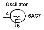
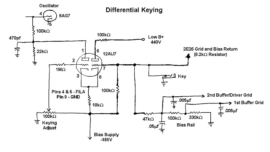
For differential keying to work, the oscillator must turn on very fast, so that it can stabilize quickly. If grid block keying is used, the bias on the oscillator is made adjustable so that it can be set to a value that just barely turns off the oscillator on key-up. When the key goes down, the bias is removed and the oscillator quickly begins to operate. In the circuit below, a 12AU7 tube is used to provide adjustable cutoff bias for the oscillator that is controlled by the key. The key also controls several other stages in the transmitter, but the circuit is arranged so that the other stages are keyed a short time after the key closes. This circuit is nearly identical to the circuit used in the Johnson Viking Ranger transmitter.
Differential/Timed Sequence
Keying
Click On A Section of the Schematic
Below for Information on That Part of the Circuit:
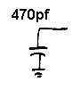
| Oscillator Grid Leak: Operating bias for the oscillator is obtained by the use of a grid leak resistor. When the oscillator grid is driven positive, some of the RF signal is rectified to DC and passes through the grid leak resistor. The DC pulses are smoothed by the grid leak capacitor and the resulting DC voltage developed across the reistor provides operating bias for the oscillator. This method of obtaining bias is known as grid leak bias. The grid leak resistor also allows the cutoff bias developed across the cutoff bias resistor to flow through to the grid of the tube and cut off the oscillator. |
 |
| Grid Leak Capacitor: The grid leak capacitor removes any RF from the voltage developed across the grid leak resistor to provide filtered grid leak bias for the oscillator. |
 |
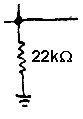
| Cutoff Bias Resistor: Current flowing through the left half of the 12AU7 tube flows through the cutoff bias resistor. The voltage drop developed across the resistor passes through the grid leak resistor and cuts off the oscillator. On key up, the current flowing through the left half of the 12AU7 is controlled by the keying adjust potentiometer. |
 |
| 1st Grid Resistor: The 1st grid resistor allows the negative cathode bias developed across the cathode resistor and the positive bias from the keying adjust potentiometer to flow through to the grid of the left section of the 12AU7. The bias on the left grid is the sum of these two voltages. |
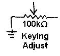
| Keying Adjust Potentiometer: The keying adjust control feeds an adjustible positive voltage to the grid of the left triode. (Remember the bias supply is positive ground.) The grid bias on the left triode is the sum of the negative voltage from the cathode bias resistor and the positive voltage from this control. By varying this control, the net grid voltage, and thus the current through the left triode (and the voltage across the cutoff bias resistor), can be controlled. In practice, this control is adjusted so that the oscillator just cuts off during key up. |
 |
| Cathode Resistor: Current flowing through both triodes flows through the cathode resistor. This produces a negative bias that is then applied to both the left and right triodes through the left and right grid resistors. When the key is closed, the current through the right triode greatly increases and the voltage across this resistor greatly increases. This increased neahtive voltage travels to the left triode grid, cutting off the left triode, and turning on the oscillator. |
 |
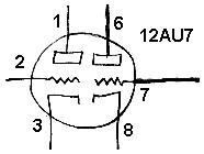
| 12AU7 Tube: The 12AU7 is a rugged, low gain (u), dual triode. The plate dissipation for each section is 2.75 watts, which is very good given the small size of the 12AU7. The 12AU7 has an amplification factor (u) of about 17 and a transconductance of about 2200 umhos. The 12AU7A and 5814A are electrically equivalent to the 12AU7 and can be used instead of the 12AU7. High gain is undesirable in this circuit, since the tube is being used only as a voltage regulator and switch. Excessive gain could lead to undesirable self oscillation. You can click here for a 12AU7A data sheet. |
|
| 2nd Grid Resistor: The 2nd grid resistor allows the negative cathode bias developed across the cathode resistor to flow through to the grid of the right section of the 12AU7. Note that positive bias flows to the right grid through either the bias railor the key, when closed. The bias on the right grid is the sum of the these two voltages. |
 |
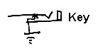
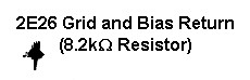
| 2E26 Grid Output: The negative voltage present at the key is connected to the final amplifier keying input. When the key is up, the negative voltage present blocks the final amplifier and shuts it off. When the key is closed, the 2E26 grid leak resistor. is connected to ground and the final amplifier is turned on. Because there are no capacitors in the line to the final amplifier, the final amplifier comes off and on directly in step with the key, without any delay. This guarantees that any chirp that occurrs in the oscillator when the key is opened is not transmitted, since the final amplifier turns off immediately, before the oscillator. Oscillator chirp that occurrs on key closure is blocked by the delay in the bias rail. |
 |
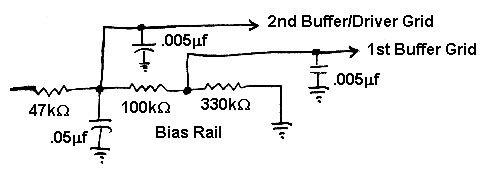
| Bias Rail Output: The negative voltage present at the key on key up is also connected to the bias rail. The bias rail is a resistor/capacitor network that outputs the grid blocking voltage to the 1st and 2nd buffer grids. When the key is up, this voltage blocks the 1st and 2nd buffers, turning them off. When the key is closed, the blocking voltage is removed from the 1st and 2nd buffers, turning them on. However, since the capacitors must discharge through the resistors, there is a slight delay in the turn on of the 1st and 2nd buffers. This delay allows the oscillator to stabilize before the 1st and 2nd buffers pass the signal. The result is that any chirp in the oscillator on key closure is not transmitted. When the key is opened, the same capacitors cause a delay in the turn off of the first and second buffers as well. However, since the final amplifier is keyed directly, it shuts of first, before the 1st and 2nd buffers, preventing any oscillator chirp from being transmitted when the key is opened. |
 |
 Back to Dr.
Greg Latta's Electrical Engineering and Amateur Radio Pages
Back to Dr.
Greg Latta's Electrical Engineering and Amateur Radio Pages
 If you have any questions or
comments, you can send E-Mail to Dr. Greg Latta at
glatta@frostburg.edu
If you have any questions or
comments, you can send E-Mail to Dr. Greg Latta at
glatta@frostburg.edu