Click here for a higher resolution (larger) schematic.
General Information:
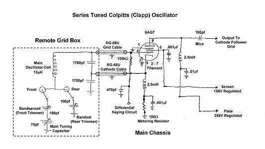
The heart of the Wingfoot VFO Exciter is, of course, the VFO itself. It is here
that the ultimate stability and sound of the transmitter are determined. The
series tuned Colpitts or Clapp oscillator is by and far the circuit of choice
for this application. The circuit features a large inductance to capacitance
(L/C) ratio which limits the current flowing in the main oscillator coil.
Limiting the current in the coil minimizes temperature changes in the coil
which lead to drift and slow chirp. The circuit also uses very small coupling
between the tuned circuit and the oscillator tube, which minimizes the effects
that changes in the tube (such as those that occur when the oscillator is
keyed) have on the frequency of the oscillator. This helps to minimize the
chirp (frequency change) that occurs when the oscillator is keyed, resulting in
a much better sounding signal.
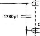
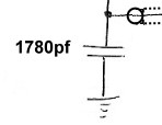
Because of the large capacitances (1780pf) that are across the tube elements
and the large inductance of the oscillator coil, it is possible to mount the LC
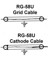
circuit in a separate cabinet called the "Remote Grid Box" and
connect it to the rest of the oscillator via shielded coaxial cables, marked
"Grid Cable" and "Cathode Cable" in the schematic.
Mounting the resonant circuit away from the heat producing main chassis
minimizes drift caused by temperature changes. Changes in room temperature
still affect the frequency of the oscillator, but these changes are much less
than those that would have been caused by the tubes and other heat producing
components on the main chassis. When the room temperature is reasonably
constant, this oscillator/VFO has a stability rivaling that of modern,
synthesized, transceivers.
Ten bandspread/bandset combinations (!) can be selected by a front panel
switch to adjust the frequencies covered by the oscillator. In practice I have
found that only need two ranges are really needed. One is set to cover between
3500kHz. and 3557kHz. This gives the most bandspread on 80m, 40m, 20m, and 15m
and is perfect for a CW operator such as myself who likes to operate at the
bottom end of the bands. Another is set for operation between 3366.7kHz to
3383.3kHz. When tripled, this yields an output between 10100kHz and 10150kHz
for operation in the 30m amateur band.
Series Tuned
Colpitts (Clapp) Oscillator
Click On A Section of the Schematic
Below for Information on That Part of the Circuit:

| Main Coil: The oscillator is the heart of the transmitter, but the oscillator coil is the heart of the heart. The coil must be constructed to minimize any changes in inductance due to temperature changes. Even the normal oscillator current in the coil can cause sufficient heating to alter the inductance of the coil. It is best to use an air core coil, since changes in the permeability of ferromagnetic materials (powdered iron, etc.) with temperature will cause changes in inductance. The wire should be as heavy and stiff as possible. In a Clapp oscillator, the tuning capacitance should be as small as possible, which requires that the inductance to be relatively large. The Wingfoot VFO uses a coil wound on a 2" diameter fiberglass form. 19 turns of #15 AWG enameled copper wire spaced over 1.5" are wound on the form. This yields an inductance of approximately 15uH. The turns are then glued in place. |
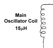
 Click on the image for a larger view. |
| Tuning, Bandspread, and Bandset Capacitors: The Wingfoot VFO transmitter uses a tuning arrangement similar to others in use at the time (1940s to 1960s) that consisted of a series/parallel arrangement of capacitors. This arrangement allows the range of frequencies covered by the oscillator to be easily adjusted. The values shown in the schematic are the maximum values for the variable capacitors. The actual value depends on the range of frequencies the operator chooses to cover. The 100pf bandspread capacitor and 75pf main tuning capacitor in series form an adjustable variable capacitor. For instance, assuming that the minimum capacitance of each capacitor is 10pf, if the bandspread capacitor is set to its minimum capacitance of 10pf, the combination will produce an effective capacitance ranging from 5pf to 8.8pf as the main tuning capacitor is varied from its minimum to maximum. If the bandspread capacitor is set to its maximum capacitance of 100pf, the combination will produce an effective capacitance of 9.1pf to 42.9pf when the main tuning capacitor is varied from its minimum to maximum. Thus, by adjusting the bandspread capacitor the change in capacitance can be varied from 3.8pf to 33.8pf. The capacitance of the bandset capacitor is added to the effective capacitance of the bandspread and main tuning capacitors and allows the maximum capacitance of the entire combination to be adjusted. For example, if the bandspread capacitor is set to 100pf (fully meshed) and the bandset capacitor is set to say, 50pf (half meshed), then the capacitance of the entire combination will vary from 59.1pf (50pf + 9.1pf) to 92.9pf (50pf + 42.9pf) as the main tuning capacitor is varied from its minimum to its maximum.. Typically, the main tuning capacitor is fully opened and the bandset capacitor adjusted to the highest frequency desired. The main tuning capacitor is then fully meshed and the bandspread capacitor is adjusted to the lowest frequency desired. This process is then repeated over and over until the desired results are obtained. |
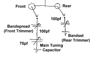 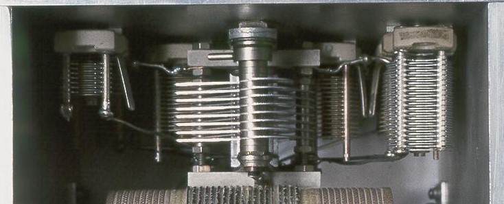 Click on the image for a larger view. |
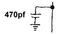
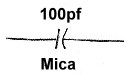
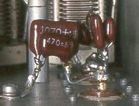
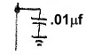
| Cathode Feedback Capacitor: The signal applied to the grid of the tube is amplified and part of the amplified signal is taken from the screen grid (not the plate) of the tube and is shunted to ground through the screen bypass capacitor. This signal must get back to the cathode of the tube, but it can't pass through the cathode RF choke, which blocks any RF. Instead, it travels from ground back through the cathode feedback capacitor to the cathode of the tube. As it travels through the feedback capacitor, it causes a small voltage to appear across the capacitor. This voltage is in phase with the oscillation in the resonant circuit and tends to assist the oscillation, restoring any energy that was lost. The voltage across a capacitor is in inverse proportion to the charge on the capacitor. Because of the large size of the feedback capacitor, only a small voltage is developed across the capacitor. This minimizes the effect of the feedback on the oscillator, keeping the feedback to a minimum. This keeps the size of the oscillation in the resonant circuit as small as possible, minimizing any heating of the main tuning coil caused by the oscillating current. The large capacitance also minimizes the effects of the connecting coaxial cable. It is this weak coupling between the resonant circuit and the output of the tube (feedback) that is another important characteristic of the Clapp oscillator. |
  |
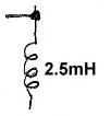
| Cathode RF Choke: Direct current must be allowed to flow to the tube cathode, but RF must be blocked so that it flows through the cathode feedback capacitor instead. This is done by connecting the cathode to ground through an RF choke, which blocks RF but passes DC. The value here is not critical. 2.5mH is a commonly available value. |
 |
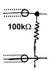
| Meter Bypass Capacitor: In a transmitter, RF can get into places it shouldn't by accident. If a meter is connected across the oscillator metering resistor to monitor the oscillator current, stray RF can get into the meter and upset the reading. The meter bypass resistor effectively short circuits to ground any RF that might try to get into the meter. |
 |
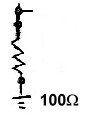
| Oscillator Metering Resistor: One of the unusual features of the Wingfoot VFO Exciter is the use of current metering resistors throughout the transmitter. One of these is included in the cathode lead of the oscillator. By connecting a voltmeter across the resistor and using Ohm's law, the total oscillator current (cathode current) can be determined. |
 |
| Screen Bypass Capacitor: The screen grid of the tube serves as the plate of the oscillator in an electron coupled oscillator. Some of the RF amplified by the tube must get back to the resonant circuit to support oscillation. The screen bypass capacitor allows the RF on the screen grid to pass through to ground while preventing the screen DC supply from being short circuited. The RF eventually flows through the cathode feedback capacitor back to the cathode of the tube. When it flows through the cathode feedback capacitor, it provides the necessary feedback to keep the oscillator going. |
 |
| Plate Bypass Capacitor: As extra insurance that any RF from the plate of the oscillator does not get into the plate power supply, a capacitor is used to short circuit any RF that might have leaked through the plate RF choke to ground. |
 |
| 6AG7 Tube: In 1950, an important article in QST magazine, "Crystal-Controlled Oscillators, A Review of Modern Crystals, Circuits and Tubes" (QST, March 1950, C. Vernon Chambers, W1JEQ) addressed several points concerning crystal oscillators, including which tube to use. In that article, various electron-coupled circuits were tried along with a variety of tubes: the 6AG7, 6F6, 6V6GT, and 6L6. Among the many conclusions in the article, one came through loud and clear, which I quote here: "Of the four tubes tested the 6AG7 is by far the best from every standpoint." As a result of that article, virtually all crystal oscillator circuits in the ARRL handbook for the next 15 years featured or recommended the use of the 6AG7. Though this oscillator isn't crystal controlled, the arguments in the article still apply, so a 6AG7 was used in this circuit. You can click here for a 6AG7 data sheet. |
 |
 Back to Dr.
Greg Latta's Electrical Engineering and Amateur Radio Pages
Back to Dr.
Greg Latta's Electrical Engineering and Amateur Radio Pages
 If you have any questions or
comments, you can send E-Mail to Dr. Greg Latta at
glatta@frostburg.edu
If you have any questions or
comments, you can send E-Mail to Dr. Greg Latta at
glatta@frostburg.edu