Click On A Section of the Schematic
Below for Information on That Part of the Circuit:
General Information:
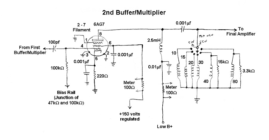
The second buffer/multiplier is also the driver for the 2E26 final amplifier.
It operates straight through on all bands except 15m and 10m. On 15m it
operates as a tripler, and on 10m it operates as a doubler. The operation and
schematic diagram for the second buffer/multiplier are essentially identical to
those of the first
buffer/multiplier, except for the addition of resistive loading on the
40m and 80m tank coils to broaden their response.
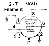
The second buffer/multiplier uses a 6AG7 with cathode bias. The bias is set so
that the amplifier does not operate as a linear amplifier. Instead, the
amplifier distorts the signal, creating higher harmonics in addition to the
fundamental frequency. The desired harmonic (or the fundamental) can then be
selected with a tuned circuit in the plate of the tube. The second
buffer/multiplier is keyed along with the oscillator, first buffer/multiplier,
and final amplifier.
Second
Buffer/Multiplier
Click On A Section of the Schematic
Below for Information on That Part of the Circuit:
| Input Coupling Capacitor: The input coupling capacitor allows the signal from the output of the 1st buffer/multiplier to pass through to the input of the second buffer/multiplier, while preventing the DC bias on the tube from flowing backwards into the 1st buffer/multiplier output. The value of this capacitor is not critical. 100pf is a commonly used value. |
 |
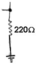
| Cathode Bias Resistor: As current flows through the cathode bias resistor it develops a voltage drop which is used to provide bias for the tube. This resistor is chosen so that when the tube is driven it is sometimes completely cutoff. This "chops" the waveform and generates the harmonics that are needed for multiplication. The voltage across the resistor is smoothed out by the cathode bypass capacitor. |
 |
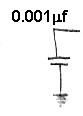
| Cathode Bypass Capacitor: The voltage developed across the cathode bias resistor will fluctuate with the output signal, giving negative feedbback, unless it is smoothed out by the cathode bypass capacitor. Another way to look at it is that the cathode bypass capacitor shunts any RF around the cathode bias resistor while preventing the flow of any direct current through the capacitor. |
 |
| 6AG7 Tube: Since the 6AG7 used in the oscillator also makes a great amplifier, it was also used in the 1st and 2nd buffer/multipliers. Using the same tube in several places is a good idea since it makes maintenance easier. The best way to check a tube is to replace it with a known good tube. If the same tube is used in several circuits, only one new tube need be kept in stock for testing purposes. You can click here for a 6AG7 data sheet. |
|
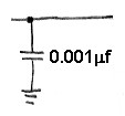
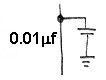
| Plate Bypass Capacitor: The plate bypass capacitor affords an extra measure of protection by shunting any RF that might have leaked through the plate RF choke to ground. The combination of the plate bypass capacitor and the plate RF choke insures that the RF doesn't get someplace it doesn't belong. |
 |
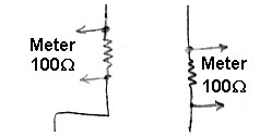
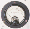
| Screen and Plate Metering Resistors: One of the unusual features of the Wingfoot VFO Exciter is the use of current metering resistors throughout the transmitter. One of these is included in the screen lead of the second buffer/multiplier and another in the plate lead. By connecting a voltmeter across the resistors and using Ohm's law, the screen and plate currents in the 2nd buffer/multiplier can be determined. |
 |
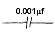
| Plate Coupling Capacitor: The plate coupling capacitor allows the RF on the plate of the tube to pass through to the plate tank circuit while preventing the DC plate voltage from reaching the tank circuit. The value of this capacitor is not critical. Any value between 100pf and 1000pf (0.001uf) is fine. The capacitor must be able to withstand the DC plate voltage on the tube. |
 |
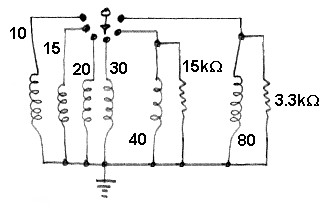
| Bandswitch: The bandswitch selects the plate tank coil to be used in the output of the 2nd buffer/multiplier. A different coil is used for each of the bands. |
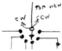
|
| Plate Tank Coils: The plate tank coil selected by the bandswitch resonates with the output capacitance of the tube at the desired frequency. The 80m and 40m coils are shunted with loading resistors to broaden their frequency response. The plate tank coils are wound on high quality ceramic coil forms and are adjustable. |
 |
 Back to Dr.
Greg Latta's Electrical Engineering and Amateur Radio Pages
Back to Dr.
Greg Latta's Electrical Engineering and Amateur Radio Pages
 If you have any questions or
comments, you can send E-Mail to Dr. Greg Latta at
glatta@frostburg.edu
If you have any questions or
comments, you can send E-Mail to Dr. Greg Latta at
glatta@frostburg.edu