
Introduction and Historical Background:
In December, 1998 I attended the annual Christmas banquet of the Cuyahoga Falls
Amateur Radio Club. At that meeting I got a wonderful Christmas present:
Jim Trutko, W8EXI, offered to give me much of his
old homebuilt ("homebrew") amateur radio equipment. He was moving
into a retirement complex and would no longer have any room to store the
equipment. He could think of no one else who might be able to do anything with
the equipment, and he didn't want to throw it out. I was very honored that
among all of the hams in the area, Jim thought I
was the only one that might be able to do something with the equipment.
Jim is now a silent key, but his spirit lives on
in the equipment that he left with me that is now restored and operating on the
air.
Among the items that he gave me were his pride and joy, the W8EXI Wingfoot VFO Exciter, an incomplete and inoperative 813 amplifier and power supply, what looked like a gutted novice transmitter, and some other small items. The W8EXI Wingfoot VFO Exciter was restored and placed back on the air in 1999. The parts from the 813 amplifier were used to build a new matching amplifier, dubbed the Wingfoot 813 Amplifier, that was placed on the air in the summer of 2000. The gutted novice transmitter, however, had to take a back seat in my junk box for a couple of years before I could get to it. In the summer of 2002 I started working on it and it was completed and back on the air in September, 2002.
These pages contain pictures of the transmitter and its various parts, circuit diagrams, circuit explanations, and the history and details of the design and construction. I hope you will find them useful.
| Front View: In this front view of the transmitter, the top and middle panels have been removed. Across the back is the power supply deck containing, from left to right, the power transformer, 5Y3 rectifier tube, OB2 regulator tube, and power supply choke. Another OB2 regulator tube is just baerly visible behind the 5Y3 tube. At the front, just visible behind the front panel, are the red tank coil and band switch on the left and the top of the 6CL6 oscillator tube on the right. |
Click on the image for a larger view. Click here for a super detailed view. |
| Front View With All Panels Installed: This is a front view of the transmitter but with all of the exterior panels installed. This keeps all of the RF inside the transmitter, and prevents any harmonics from being radiated by the transmitter. This lessons the possibility of television interference (TVI). Such shielding is expensive and is unusual in a homebrew transmitter of this type. |
 Click on the image for a larger view. Click here for a super detailed view. |
| Front Panel: The front panel is machined out of brushed aluminum. Knob and jack functions are stamped directly into the aluminum with 1/8" high metal stamps. The transmitter is bandswitched and covers 80, 40, 30, 20, and 15 meters. The band switch is the knob in the middle. At the upper left are the SO-239 RF output connector and the 1/4" key jack. The two knobs on the bottom adjust the pi-network matching circuit. The knob at lower left is the antenna loading adjustment, and the knob at lower right is the plate tuning adjustment. The crystal socket is the white ceramic socket at the lower right. Since Jim, W8EXI, had originally built parts of the transmitter and had mounted a laminated callsign plaque on the transmitter, I decided to retain his plaque and eventually add a plaque with my callsign as well. |
 Click on the image for a larger view. Click here for a super detailed view. |
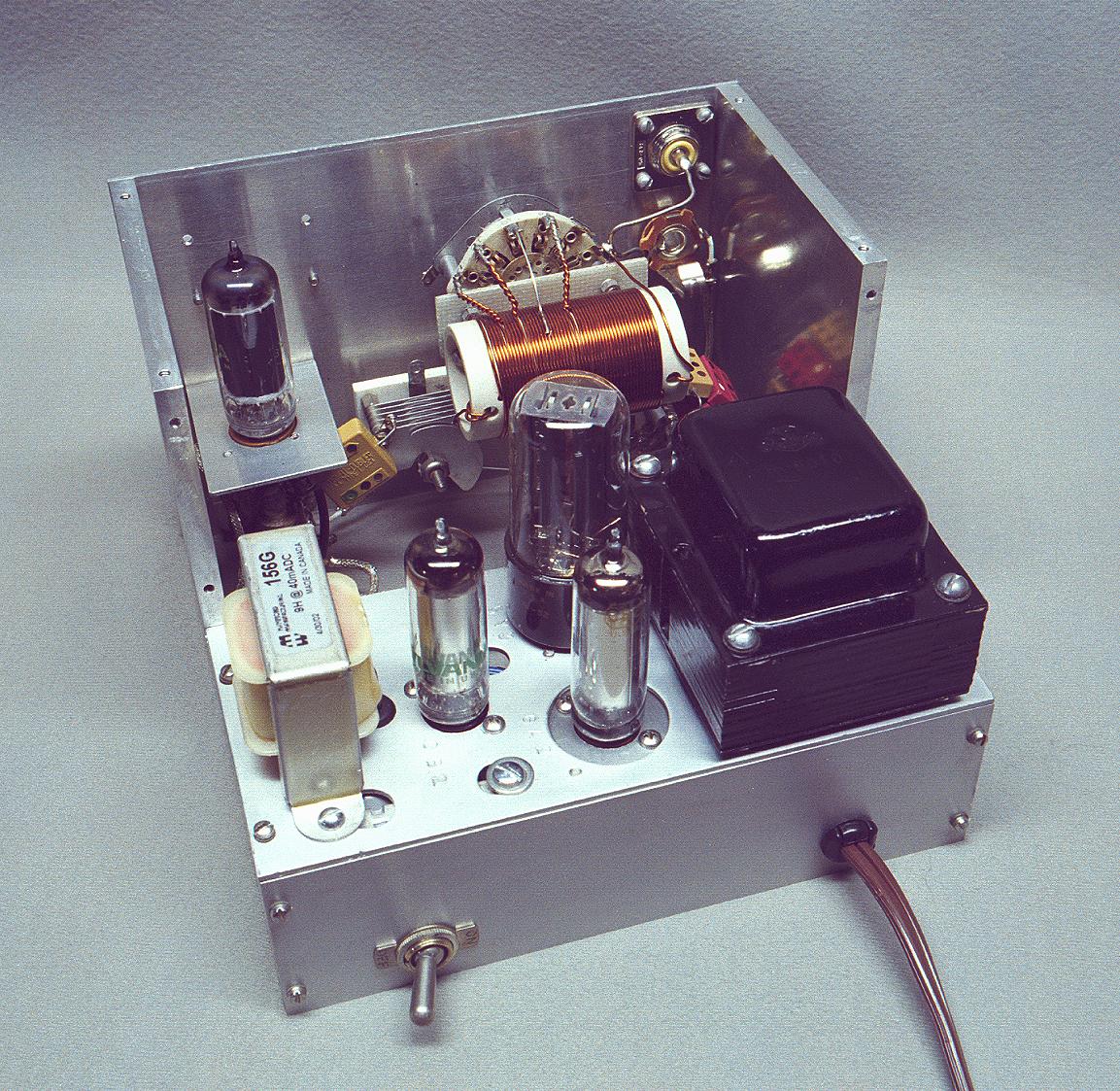
| Rear View: This is a rear view of the transmitter with the top and middle panels removed to reveal the interior of the transmitter. At the rear the power supply deck is clearly visible. It contains, from left to right, the power tupply choke, 1st 0B2 regulator tube, 5Y3 rectifier tube, second 0B2 regulator tube, and power transformer. The RF components are mounted on the front panel. From left to right the 6CL6 oscillator tube, plate coupling and plate tuning capacitors, bandswitch and RF tank coil, and output connector and key jack, are visible. |
 Click on the image for a larger view. Click here for a super detailed view. |
| Rear View With Parts Labeled: This is is the same view as the previous photo but with all of the transmitter parts labeled. |
 Click on the image for a larger view. |
| Rear View With All Panels Installed: This is a rear view of the transmitter but with all of the exterior panels installed. This keeps all of the RF inside the transmitter, and prevents any harmonics from being radiated by the transmitter. This lessons the possibility of television interference (TVI). Such shielding is expensive and is unusual in a homebrew transmitter of this type. |
 Click on the image for a larger view. Click here for a super detailed view. |
 Click here for pictures and information on the Wingfoot
VFO 2E26 Exciter
Click here for pictures and information on the Wingfoot
VFO 2E26 Exciter Click here for pictures and information on the Wingfoot
813 Amplifier
Click here for pictures and information on the Wingfoot
813 Amplifier Back to Dr.
Greg Latta's Electrical Engineering and Amateur Radio Pages
Back to Dr.
Greg Latta's Electrical Engineering and Amateur Radio Pages
 If you have any questions or
comments, you can send E-Mail to Dr. Greg Latta at
glatta@frostburg.edu
If you have any questions or
comments, you can send E-Mail to Dr. Greg Latta at
glatta@frostburg.edu
This page is under constant revision. Please check back often.