
| Introduction and
Front and Side View
Photos |
Power
Supply, Interior, and Rear View Photos |
| Schematic Diagrams and Circuit
Descriptions |
Special
Features |
| Block Diagram |
Chassis Layout |
| The W8EXI Wingfoot VFO Exciter (transmitter) was built and
designed by Jim Trutko, W8EXI (now, sadly, a silent key), in the middle to late
1950's with the assistance of the Goodyear Aerospace machine shop in Akron,
Ohio. It is a very rare example of a homebuilt ("homebrew" in the
lingo of amateur radio operators), state of the art, 1950's high frequency
transmitter of the frequency multiplying type. It is the only one in existence.
It was restored and redesigned in 1999-2000 by Greg Latta, AA8V. In these pages are pictures of the transmitter and its various parts, circuit diagrams, circuit descriptions, and a history of the restoration and redesign. |
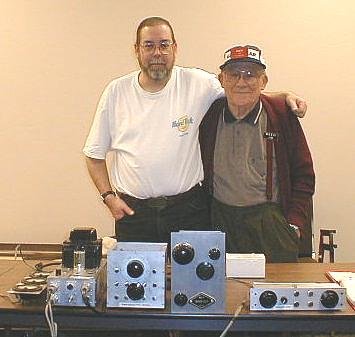 |
| After restoring the Wingfoot VFO transmitter, I designed amd built a matching Wingfoot 813 Amplifier featuring an 813 beam power tube in grounded grid. The two units together make a wonderful combination with a conservative output of 250 watts. | The author (left) and Jim Trutko (right) at a presentation on the Wingfoot VFO Exciter for the Cuyahoga Falls Amateur Radio Club. All of the components of the restored exciter are visible on the table. From left to right the components are: meter panel, power supply, grid box, main chassis, remote control. |
This page is dedicated to Jim Trutko, W8EXI, who was a shining example of what every amateur radio operator should be. We miss you Jim!
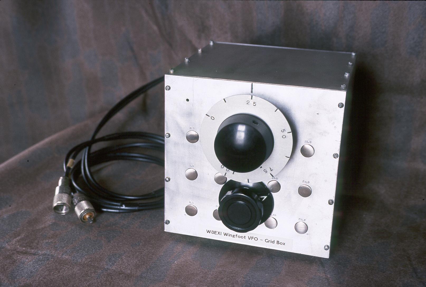
| Exciter Grid Box: This is the "Grid Box", where the signal starts. This chassis contains the LC circuit (i.e. the coil and variable capacitor) for the Clapp variable frequency oscillator. It contains no tubes or transistors. Besides the coil and the variable capacitor it also contains twenty air trimmer capacitors and a band switch so that the bandspread can be adjusted over ten different ranges, originally the CW and phone segments of the 80, 40, 20, 15, and 10 meter amateur bands. It connects to the main chassis (which contains the 6AG7 oscillator tube) through a pair of coaxial cables. The chassis itself is built out of 3/8 inch aluminum, which makes it very, very strong and very rigid. With constant room temperature drift is as small as or less than that of modern rigs. |
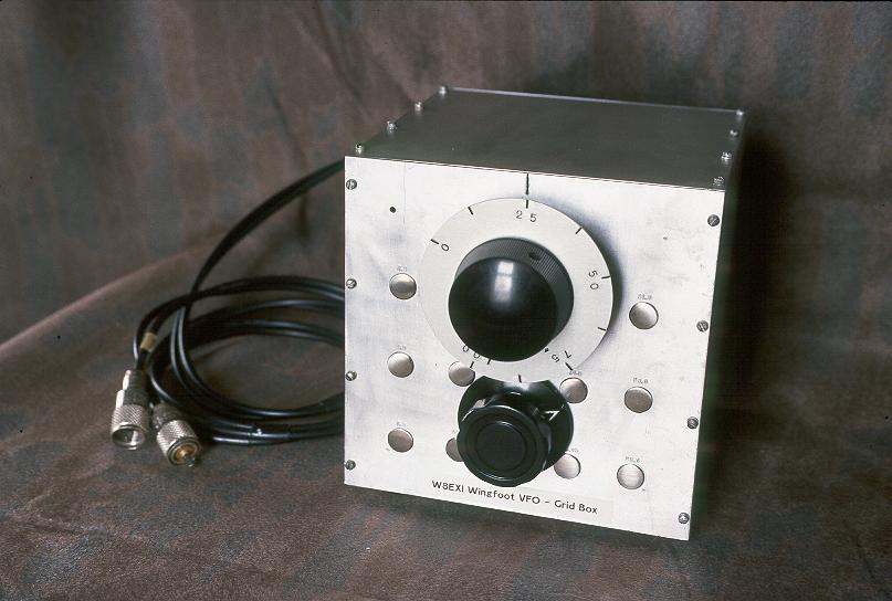 Click on the image for a larger view. Click here for a super detailed view. |
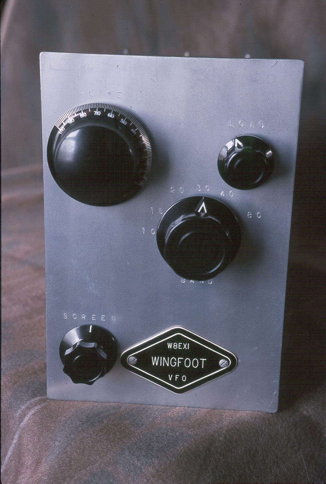
| Exciter Front Panel: The front panel of the exciter contains four controls. At the upper left is the plate tuning control, which uses a five to one planetary reduction drive. The plate loading control is at the upper right, and the band switch is below the plate tuning and load controls. The band switch is a six position switch, which allowed for the addition of the 30m band during the restoration. The final screen control, which controls the power output, is at the lower left. The diamond shaped plaque on the front which says "W8EXI Wingfoot VFO" is the same shape as the "Winged Foot" logo that the Goodyear Tire and Rubber Company used in the 1950's. The embossing of the control functions on the front panel was done as part of the restoration. |
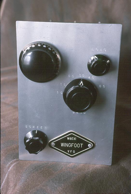 Click on the image for a larger view. Click here for a super detailed view. |
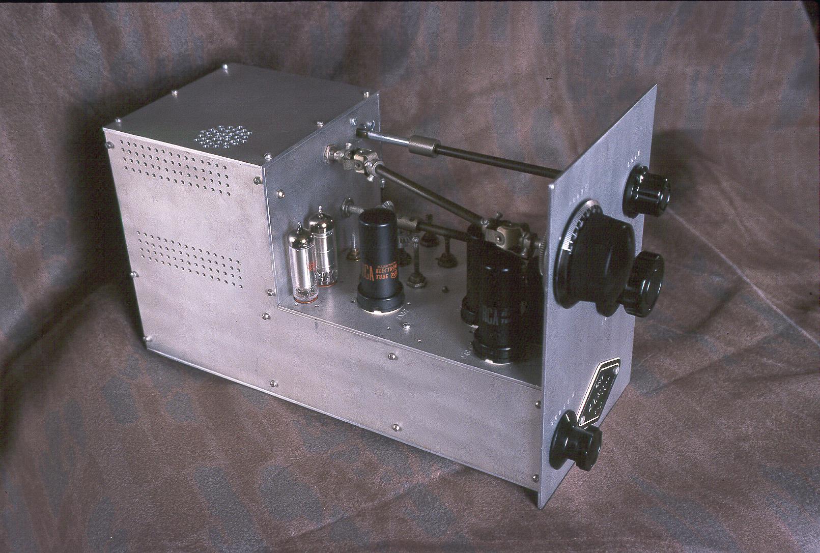
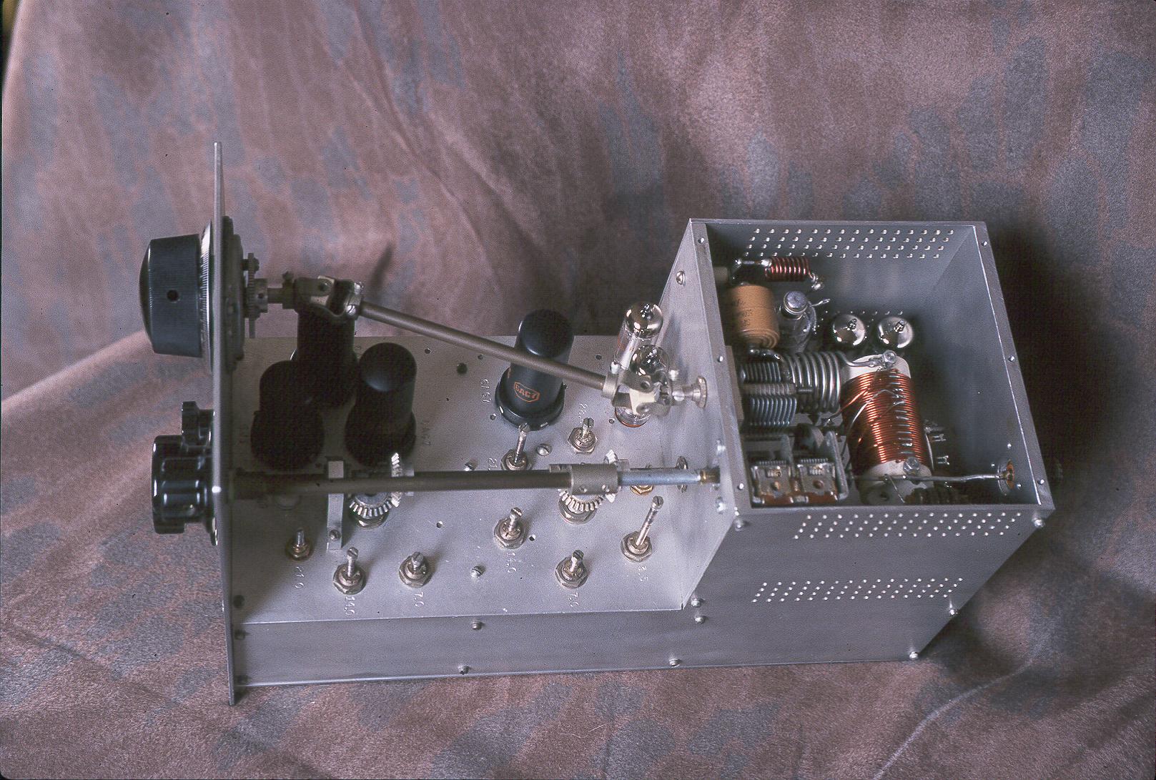
| Exciter Left Side View: In this view of the exciter from the left side the cover is on the final amplifier compartment, as it normally would be during operation. The two voltage regulator tubes can be seen at the left. The lone metal tube just to the right of them is the 6AG7 2nd buffer/multiplier. The 6AG7 1st buffer/multiplier, 6AG7 Clapp oscillator, and 6J5 cathode follower tubes are clustered in a triangle just behind the front panel. Note the pair of universal joints used to connect the plate tuning control on the front panel to the shaft of the plate tuning capacitor at the rear. The plate tuning control is a National planetary drive with a five to one reduction ratio. This makes plate tuning very easy. |
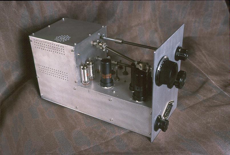 Click on the image for a larger view. Click here for a super detailed view. |
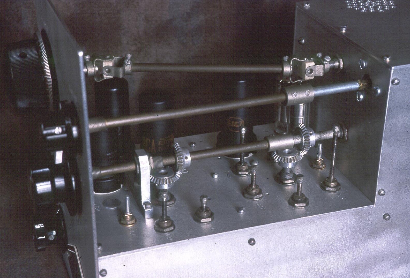
| Exciter Right Side View: The mechanics of the Wingfoot Exciter are quite involved. The plate tuning control (at the top of the front panel, towards the back of the photo) features a National planetary reduction drive on the front panel, which then connects to the plate tuning capacitor at the rear through a pair of universal joints and a long shaft. The plate loading control (at the top of the front panel, towards the front of the photo) connects to the loading capacitor at the back via a long shaft and a 1/4" straight coupling. The band switch in the middle of the front panel controls three separate switches. The 1st buffer/multiplier and driver stage switches are operated through right angle couplings mounted on the band switch shaft. The final amplifier bandswitch is connected directly to the shaft at the rear. |
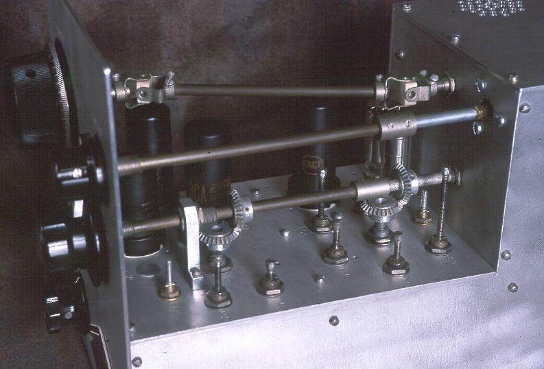 Click on the image for a larger view. Click here for a super detailed view. |
| Exciter Top View: This is the main chassis of the exciter as viewed from above. In the triangle of tubes on the left, the 6AG7 Clapp oscillator tube is at the top, the 6J5 cathode follower is on the left, and the 6AG7 first buffer/multiplier is on the right. To the right of the triangle is the 6AG7 2nd buffer/multiplier tube and a pair of voltage regulator tubes are just to the left of the final amplifier compartment. Inside the final amplifier compartment is the 2E26 final amplifier tube on the left and a pair of 5814 (12AU7) tubes on the right. One 5814 is used for the differential keying and the other is used to control the screen grid of the 2E26 final amplifier. Note the use of 1/4 inch aluminum for the bulkheads. |
Click on the image for a larger view. Click here for a super detailed view. |
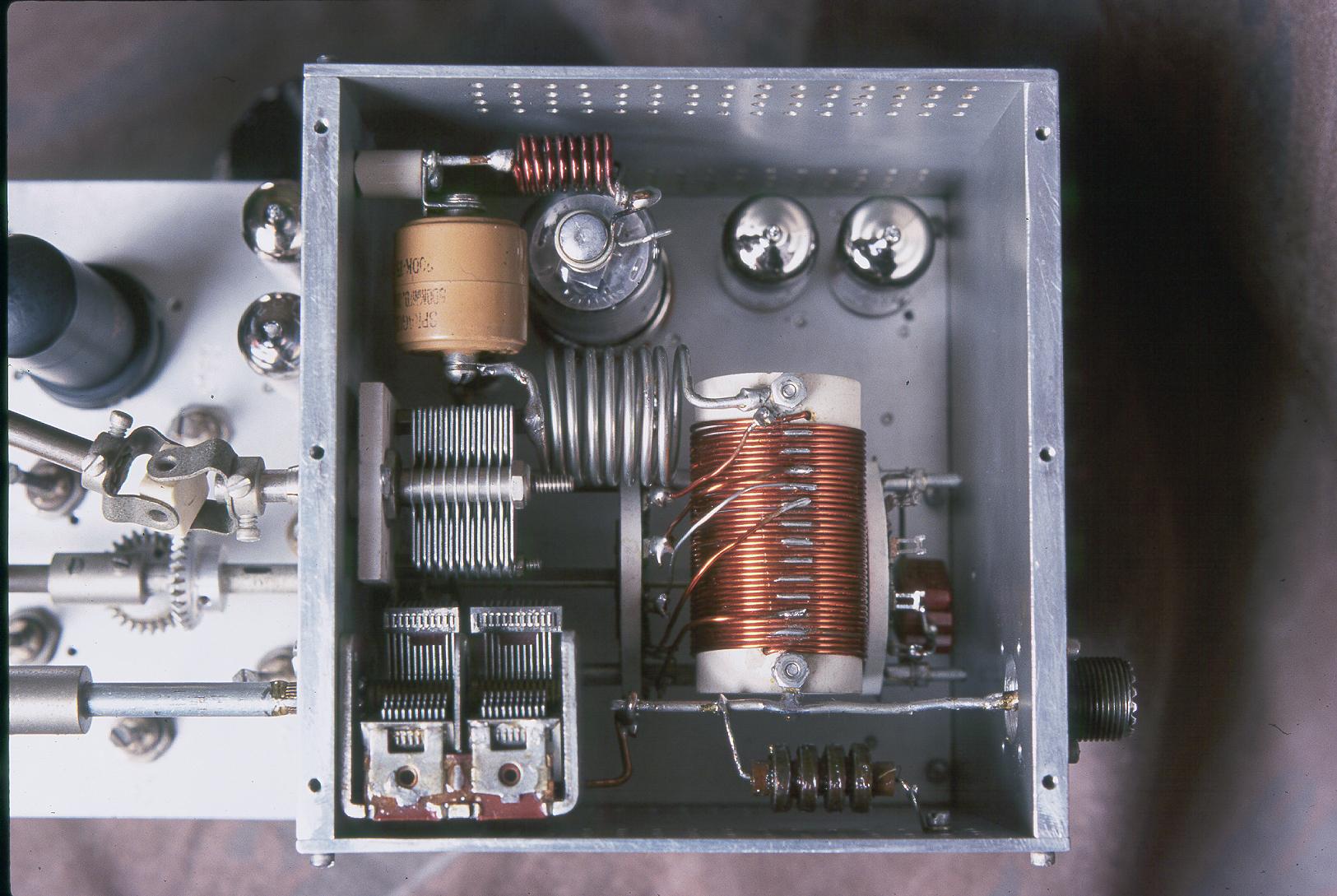
| Exciter Top View - Final Amplifier Compartment: This is a close up view of the final amplifier compartment. (The compartment is normally covered, but the cover has been removed to show the interior.) The 2E26 final amplifier tube is at the upper left of the compartment, and the 5814 (12AU7) differential keying and final amplifier screen control tubes are at the upper right. The plate tuning capacitor is on the left half way up with a universal joint on its shaft that connects it, via an aluminum shaft, to the front panel. The plate loading capacitor is the double section capacitor at the lower left The bandswitch is visible under the plate tank coil. |
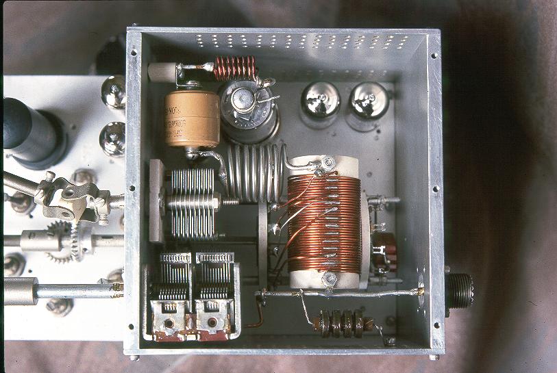 Click on the image for a larger view. Click here for a super detailed view. |
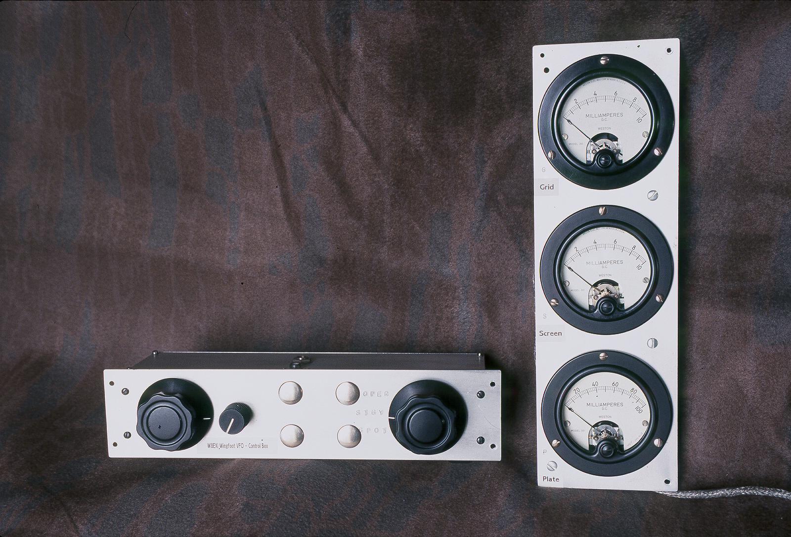
| Exciter Remote Control And
Meter Panel: This picture shows the remote control unit for the exciter and the meter panel. The remote control on the left offers three modes: Operate, Standby, and Spot. In Operate, all stages are active. In Standby, only filament voltages are activated, and the exciter plate supply is disabled, which keeps heating in the power supply to a minimum. In Spot mode, the final amplifier is disabled, but all other stages are active, which allows the operator to hear the exciter signal in the station receiver. The meter panel simultaneously shows the final amplifier grid, screen, and plate currents on Weston type 301 milliammeters. Weston type 301 meters were among the best. Back in 1967, a single meter cost $14.40 from Allied Electronics, equivalent to about $85 today. Note the shielded wire used to connect the meter panel to the exciter. |
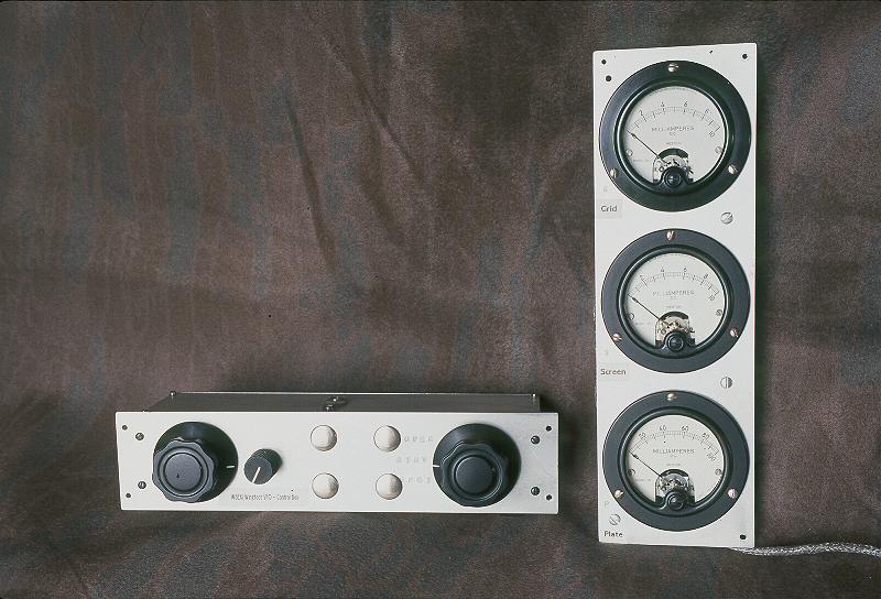 Click on the image for a larger view. Click here for a super detailed view. |
 Click here for pictures and information on the matching Wingfoot 813
Amplifier
Click here for pictures and information on the matching Wingfoot 813
Amplifier Back to Dr.
Greg Latta's Electrical Engineering and Amateur Radio Pages
Back to Dr.
Greg Latta's Electrical Engineering and Amateur Radio Pages
 If you have any questions or
comments, you can send E-Mail to Dr. Greg Latta at
glatta@frostburg.edu
If you have any questions or
comments, you can send E-Mail to Dr. Greg Latta at
glatta@frostburg.edu