
| Main Page and Front and Side Views | Tank Coil Information |
| Interior and Back Views | Typical Operating Conditions |
| Circuit Description and Schematic Diagram | Power Supply Photos |
| 813 Tube Information | Power Supply Circuit Description and Schematic Diagram |
Important Safety Note: Working on or testing equipment such as the 813 amplifier and its matching power supply is extremely dangerous since very high voltages are present when the equipment is turned on, and may even be present when the equipment is turned off and unplugged. If at all possible, do all work with the equipment off and unplugged and be sure that the capacitors are properly discharged before working on the equipment. The operator assumes all risk and liability in such matters! Do not work on this type of equipment unless you are experienced with working around very high voltages!
The W8EXI Wingfoot VFO Exciter was built and designed by Jim Trutko, W8EXI (now a silent key), in the middle to late 1950's with the assistance of the Goodyear Aerospace machine shop in Akron, Ohio. It is a very rare example of a homebuilt ("homebrew", in the lingo of amateur radio operators), state of the art, 1950's high frequency transmitter of the frequency multiplying type. It is the only one in existence. I restored and redesigned it in 1999-2000.
At the time I received the exciter, I also received an amplifier that Jim had been working on years earlier. Designed around the popular (in the 1950's) 813 beam power tetrode, the amplifier was unfinished and incomplete. There was also a power supply for the amplifier on a separate chassis, but the power supply had defective parts (particularly the filter capacitors) and was not operational.
Since the amplifier would make a beautiful companion to the exciter, I decided to repair and redesign the power supply, and then to completely disassemble the amplifier into a pile of parts and start completely over. The result is an amplifier of exceptional performance and beauty.
These pages contain pictures and explanations of the amplifier and its various parts, circuit diagrams, circuit explanations, and a history of the design and construction of the amplifier.
This page is dedicated to Jim Trutko, W8EXI, who was a shining example of what every amateur radio operator should be. We miss you Jim!
| Amplifier Front: This is the front of the finished amplifier. A plaque in the shape of the trademark Goodyear diamond of the 1950's was made and fitted to the front panel. This matches a similar plaque on the exciter. Control functions are hand stamped into the front panel. The large graduated knob is the plate tuning control. This has a resetability of 1 part in 200. The loading control is the smaller knob below the plate tuning control. It is not indexed, since it is always tuned for maximum output. The band switch on the left is simply labeled A, B, C, D, E, so that the taps on the tank coil can be changed without relabeling the front panel. The knob at bottom selects the amplifier mode: Off, Standby, or Operate. A pair of lamps to the right of the mode switch indicates which mode the amplifier is in. The high voltage safety cage, which has been removed in the other photos, is also visible here. |
 Click on the image for a larger view. Click here for a super detailed view. |
| Amplifier Left Side: In this view of the amplifier, the gray transformer at the rear is the filament transformer which delivers 5 amperes at 10 volts to the 813 filament. In front of the transformer is a relay which switches the amplifier in and out of the feed line. This allows the amplifier to be used with transceivers. To the right of the relay is the plate RF choke (made by National) and the plate tank coil. The bandswitch is between the tank coil and the front panel. Behind the tank coil are the plate tuning capacitor (at the top) and the plate loading capacitor (at the bottom) On the rear panel can be seen the Amphenol aircraft style connectors which are also used on the exciter. The red and black connectors on the rear panel carry the plate high voltage. |
 Click on the image for a larger view. Click here for a super detailed view. |
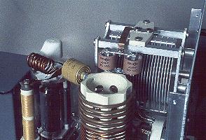
| Amplifier Plate Circuit Top View: In this top view of the plate circuit the top of the plate RF choke (wound with gold colored wire) is visible at the left. The plate RF choke allows the 2000 volt plate potential to reach the tube, while preventing the RF produced by the tube from reaching the power supply. Just above the RF choke and in front of the white ceramic tube plate connector is a small coil of heavy copper wire. This is a parasitic surpressor, which helps to prevent undesired oscillations in the amplifier. Between the parasitic surpressor the the large plate tank coil is the yellow plate coupling capacitor, which keeps the 2000 volt plate potential from reaching the plate tank circuit. Just above the plate tank coil are two 40 uuf "door knob" capacitors connected in parallel. These are then connected in series with the large plate tank capacitor visible behind them to slow down the tuning rate of the plate tuning capacitor. |
 Click on the image for a larger view. Click here for a super detailed view. |
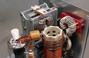
| Amplifier 80m Toroid: When first built, the amplifier only operated on the 40m, 30m, and 20m bands. The original tank coil lacked sufficient inductance to tune the 80m band. 80m capability was added to the amplifier in 2013 by adding a toroidal inductor (L1) in series with the original tank coil. The inductor was made by winding 30 turns of #18 insulated wire on a T-184-6 (yellow) form. The inductor was then mounted on the back of the front panel using a piece of plastic sheet and a couple of cable ties, as can be seen in the photo at right. The toroidal inductor alone does not tune 80m. It is the combination of the original coil and the toroidal inductor in series that tunes 80m. |
 Click on the image for a larger view. Click here for a super detailed view. |
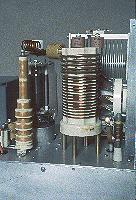
| Amplifier Plate Circuit Side View: In this side view of the amplifier plate circuit, the complete plate RF choke is at the left, and the complete tank coil is visible in the center of the photo. The tank coil consists of copper wire and tubing wound on a ceramic form. The coil is mounted off of the chassis on brass spacers. Taps on the coil are connected to the bandswitch at right with copper strapping or copper braid. In front of the band switch, at far right, just behind the front panel, is the antenna RF choke. This is connected between the output antenna connector and ground and serves two purposes: 1. It grounds the plate loading capacitor for DC so that the loading capacitor need only handle the output RF; 2. It short circuits the plate supply in the event of a short in the plate coupling capacitor. This will blow a fuse and prevent the 2000 volt plate potential from reaching the antenna system. |
 Click on the image for a larger view. Click here for a super detailed view. |
| Amplifier Right Side: This photo, taken on the other side of the amplifier, clearly shows the plate tuning and loading capacitors on the left. The plate capacitor (with the larger spacing) is at top, and the loading capacitor is at the bottom, resting on the chassis. The 813 beam power tube, an RCA with a graphite plate, is also nicely shown. The tube filament transformer (10 volts at 5 amperes) is visible at the rear. The output of the amplifier on 80m, 40m, 30m, and 20m, is more than 250 watts, though in typical operation output is limited to 250 watts. No forced air cooling is used. The tube is adequately cooled by convection. |
 Click on the image for a larger view. Click here for a super detailed view. |
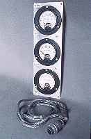
| Amplifier Meter Panel: Plate, screen, and grid currents are separately metered on the amplifier. The meter panel consists of three Weston meters vertically mounted. The meters are connected to the amplifier via a shielded cable and an Amphenol aircraft style connector. Since this photo was taken, metal cabinets have been made for the exciter and amplifier meter panels which allow them to stand on their own, without being mounted to a panel. The cabinets match the construction of the exciter and the amplifier. The individual meters were disassembled and cleaned inside and out. |
 Click on the image for a larger view. Click here for a super detailed view. |
 Click here for pictures and information on the matching Wingfoot VFO
2E26 Exciter
 Back to Dr.
Greg Latta's Electrical Engineering and Amateur Radio Pages
 If you have any questions or
comments, you can send E-Mail to Dr. Greg Latta at
glatta@frostburg.edu
This page is under constant revision. Please check back often.