Click On Any Section of the Schematic
Below for Information on That Part of the Circuit:
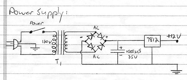
Power Supply:
You will need some sort of power supply to power the system. The power supply
specifications are very forgiving. Any output voltage large enough to reliably
trip the 12V timer relay you
plan to use will be fine. I had a transformer that after rectification and
filtering only gave me about 11V. I ran it through an 8V regulator and that
worked fine with my 12V relay and the other circuits.
You could of course use a 9V to a 12V wall wart, and that might save you some
space inside the cabinet. The system draws very little current, so just about
any wall wart would work, as long as the output is between 9V and 12V DC.
If you want to use an internal power supply, the following example will work
fine:
Power Supply Circuit
Click On Any Section of the Schematic
Below for Information on That Part of the Circuit:
Line Cord:
The line cord should be of the grounded type. The supply draws very little
current, so just about any grounded cord can be used. The black (hot) lead
should go to the switch, and the white (neutral) lead should go to the
transformer. For use in the CW TR System, see the
AC wiring page.
Power Switch:
The power supply draws so little power that just about any switch that can
handle 120V can be used. I used a small toggle switch with a rating of 1A. See
the AC wiring page.
T1 Transformer:
The maximum voltage that the series regulator can accomodate is 35V. Since the
capacitor may charge to the peak AC voltage, this implies a maximum of about 25
volts for the transformer. For the minimum, the best thing to do is to wire up
whatever transformer you have to the diodes and filter capacitor and see if you
get at least 14V. You will need at least 14V to drive a 7812 12V regulator.
Though 12V is technically needed for the
12V timer relay, many 12V
relays will work on less, and the other circuits will also work on less. Test
your 12V relay. If it reliably works on less than 12V then you can use a lower
voltage transformer and series regulator. For example, my relay worked on 8V,
and my transformer only put out about 11V with the diodes and rectifier in
place, so I used a 7808 8V regulator for an 8V supply. Everything worked fine.
Four Diodes/Bridge Rectifier:
The diodes that are used here can be any of the 1N400X type, such as the
1N4002, 1N4007 etc. If you happen to have a bridge rectifier, you can use that
instead. The voltage and current are so low that just about any bridge
rectifier will work.
1000uf Filter Capacitor:
The filter capacitor should have a sufficient voltage rating to sustain the
voltage across it. The voltage across it will be a maximum of 1.4 times the
transformer voltage. As to capacitance, I used a 1000uf unit I had on hand.
More capacitance is fine but not necessary, and less, such as 250uf or 500uf,
might also work.
7812 Series Regulator:
The maximum voltage out of the supply should be 12V, since a 12V relay is used.
However, many 12V relays, and the circuits as well, will work on as little as
8V. Any regulator at least 2V less than the loaded output on the filter
capacitor should work, down to an 8V regulator. This means you can use a 7812,
7809, or 7808 regulator. So little current is drawn it is not necessary to heat
sink the regulator.
 Back to Dr. Greg Latta's
Electrical Engineering and Amateur Radio Pages
Back to Dr. Greg Latta's
Electrical Engineering and Amateur Radio Pages
 If you have any questions or
comments, you can send E-Mail to Dr. Greg Latta at
glatta@frostburg.edu
If you have any questions or
comments, you can send E-Mail to Dr. Greg Latta at
glatta@frostburg.edu