Click on the image for a larger view.
Click here for a super detailed view.
Click on the image for a larger view.
Click here for a super detailed
view.
|
|
Introduction:
I love old gear, especially tube gear. As a novice, I started with a
Hallicrafters S-120 receiver and an Ameco AC-1 transmitter. To handle the
transmit receive switching I used a ceramic knife switch I purchased at the
local hardware store. Over the years I progressed to better equipment and
started using a Dow-Key antenna changeover relay actuated by the transmitter.
Eventually, I graduated to a modern transceiver with completely automatic
transmit/receive switching. Just touch the key, and I was transmitting.
Even though I had modern equipment, I still preferred to use the vintage tube gear. To me it was more fun and more of a challenge. However, the homebrew and vintage transmitters I was using sometimes lacked any kind of transmit/receive switching circuit, and I was back to manual T/R switching. I quickly found that automatic T/R switching had spoiled me, and I decided to design and build an automatic T/R system that would work with ANY transmitter and receiver combination. The result was this unit.
Design Specifications:
The specifications of the unit are as follows:
1. The unit is small in size.
2. It connects between the key and the transmitter. The key plugs into the
unit, and the unit plugs into the transmitter.
3. It is positively keyed, so keyers without negative keying outputs can be
used with it.
4. Though positive keyed, it can key both positive and negative keyed
transmitters.
5. It runs on 120V AC. No batteries are required.
6. It has a timer/hold circuit that actuates the moment the key is pressed, and
stays engaged for an adjustable hold time after keying stops.
7. A switch can disable the timer/hold circuit or set it to hold indefinitely.
8. The timer/hold circuit controls a 120V outlet, into which an external T/R
relay, such as a Dow-Key coaxial relay, is plugged.
9. The timer/hold circuit changes the state of normally closed (NC) and
normally open (NO) outputs to facilitate receiver muting and other similar
functions.
10. The unit has a sidetone generator and self contained speaker with
adjustable volume and pitch controls.
11. A switch can turn the sidetone off and on.
12. It is solid state and uses readily available parts. It does not use any
programmable devices or other specialized parts.
Overall Circuit Description:
The Automatic CW T/R system contains four circuits:
1. Timer/Hold Circuit: The
timer/hold circuit is the heart of the system. Whenever the key is pressed the
timer is activated and a relay is closed. The timer remains activated and the
relay closed until the operator stops sending. The relay remains closed for an
adjustable hold time after the operator stops sending, as in a modern
transceiver.
2. Sidetone Circuit: The
sidetone circuit generates an audio tone with adjustable pitch and volume
whenever the key is pressed.
3. Keying Inverter: The
keying inverter allows the unit to key negative keyed transmitters in addition
to positive keyed transmitters.
4. Power Supply: The
power supply runs on 120V AC and provides regulated power to run the other
circuits in the system.
The Circuits Are Independent Of Each
Other:
The circuits in the T/R system are independent of each other. This means
that if you only want the timer/hold function, you do not have to build the
sidetone or keying inverter circuits. Likewise, if you just want to add a
sidetone to your keying, you can just build the sidetone circuit and so on.
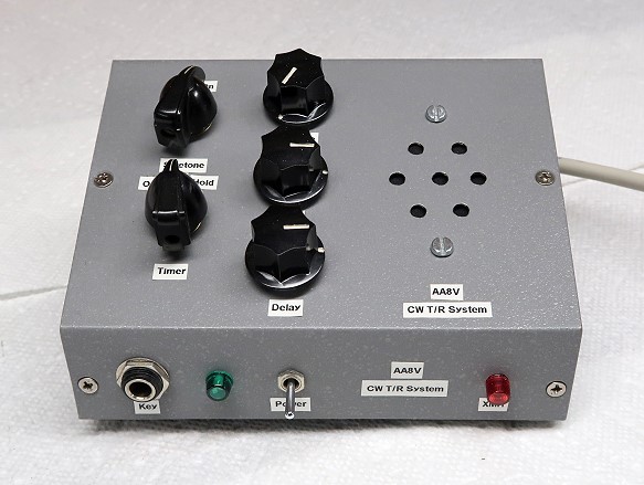
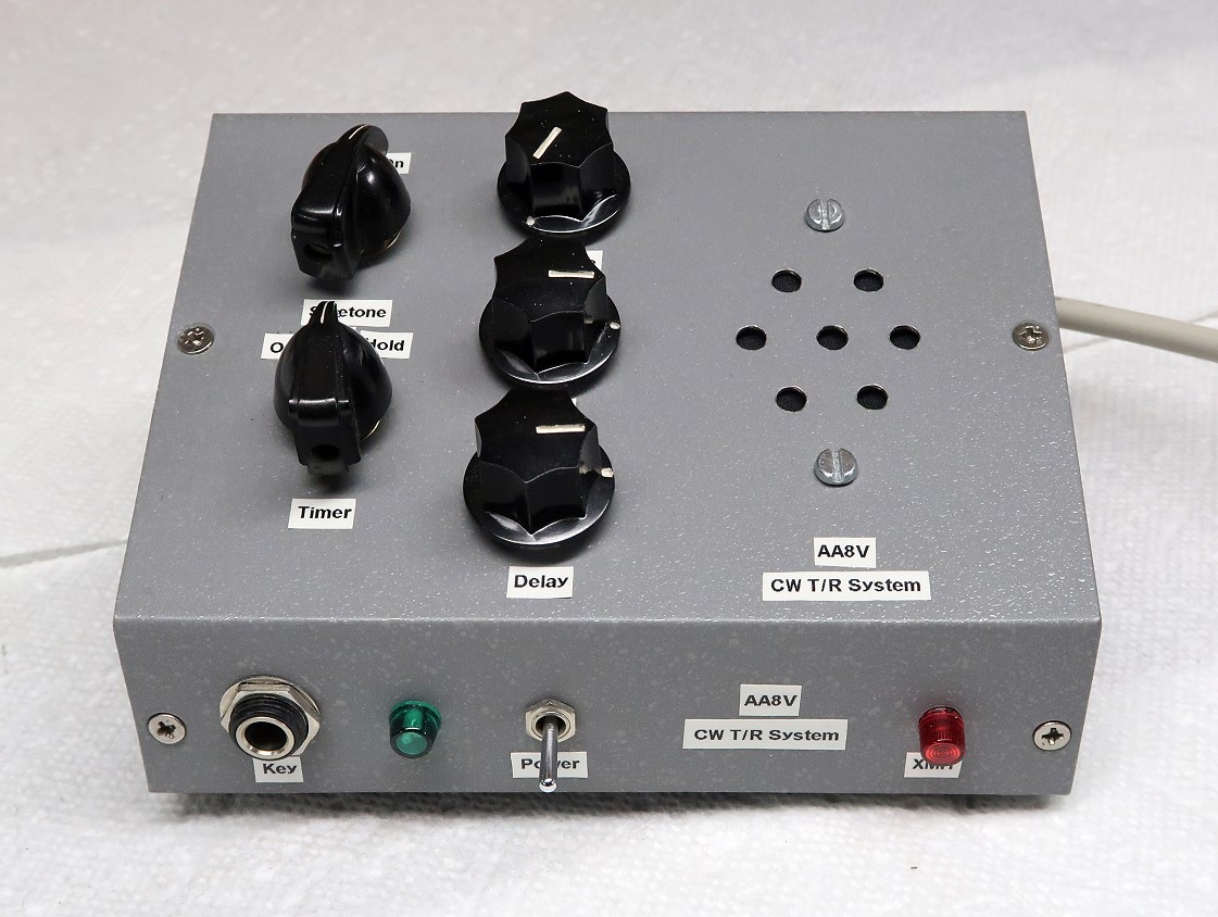
| Overall View: The T/R system is built in a small sloping cabinet that I happened to have on hand. It was a tough job fitting everything inside this cabinet, but worth the effort. However, it is literally crammed full. I would recommend a slightly larger enclosure if you have one available. This would give you a little more room to move around in. You have to fit in two relays, the circuits and power supply, and still have room for the speaker and connectors. |
Click on the image for a larger view. Click here for a super detailed view. |
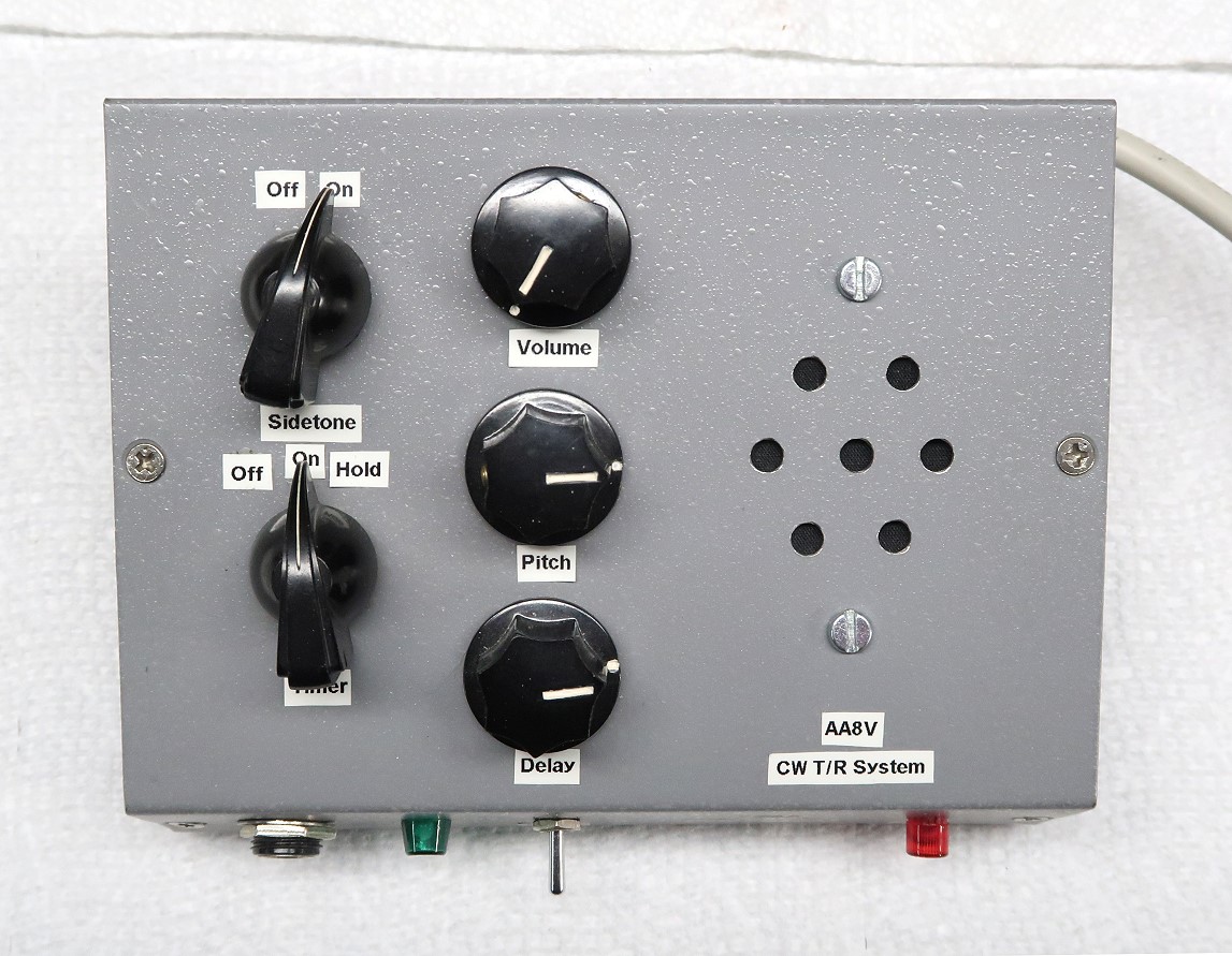
| Top View: In this top view all of the switches and knobs are clearly visible. At top left is the switch that turns the sidetone off and on. Below the sidetone switch is the timer function switch. This has three positions: Off, On, and Hold. The timer can be turned off when only the sidetone or keying inverter functions are desired. When placed in hold, the unit is placed in transmit mode indefinitely. This can be useful when tuning up. The top two controls in the middle control the volume and pitch of the sidetone generator. The bottom knob controls the delay time (hold) time, the amount of time the unit stays in transmit after the operator stops sending. Seven holes were drilled to accomodate the speaker. |
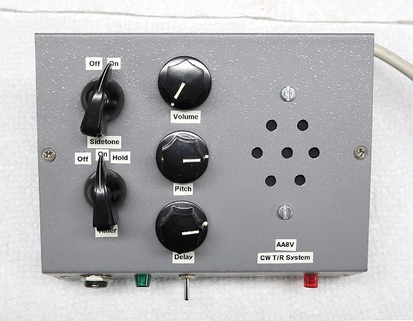
Click on the image for a larger view. Click here for a super detailed view. |
| Rear View: The rear panel of the T/R system contains the various outputs. The 120V AC outlet at top left is activated in transmit. This is used to activate a 120V Dow-Key antenna changeover relay. If a cube tap is used here, an "On The Air Light" could also be activated in transmit mode. Current should be limited to about 1A. The state of the connectors at bottom right is changed when in transmit. For example, I use the NC (normally closed) connector to mute my receiver. I have the receiver mute circuit of my 6x2 (or Hallicrafters SX-96) connected to the NC connector. When the system goes into transmit, the NC connector is opened, muting the receiver. Likewise, the NO (normally open) circuit closes in transmit, and could be used for a variety of functions. The keying outputs are connected to the key jack on the transmitter. The XMTR+ output is used with positive keyed transmitters, and the XMTR- output is used with negative (grid block) keyed transmitters. |
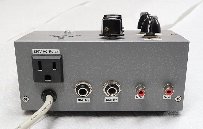
Click on the image for a larger view. Click here for a super detailed view. |
| Front View: A key, keyer, or bug is plugged into the key jack on the front of the unit. The unit is positive keyed, so it is compatible with any keyer. The power switch turns the unit off and on, with a green pilot light showing when the unit is on. A red LED lights whenever the system is in the transmit mode. |
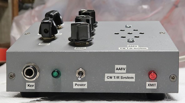 Click on the image for a larger view. Click here for a super detailed view. |
 Back to Dr.
Greg Latta's Electrical Engineering and Amateur Radio Pages
Back to Dr.
Greg Latta's Electrical Engineering and Amateur Radio Pages
 If you have any questions or
comments, you can send E-Mail to Dr. Greg Latta at
glatta@frostburg.edu
If you have any questions or
comments, you can send E-Mail to Dr. Greg Latta at
glatta@frostburg.edu