Click here for a higher resolution (larger) schematic.
Introduction:
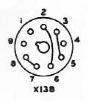
The accessory socket on the Viking Ranger is a 9-pin (not octal) socket that
provides connections to the transmitter power supply and the modulation
transformer secondary. A 9-pin plug normally connects the power supply and
modulation transformer secondary to the internal transmitter circuits via
three jumpers. The transmitter will not operate
normally without the plug installed. 9-pin plugs are very hard to find, so
treat the plug with care! If the plug is missing, the jumpers can be installed
internally, but it is best to use the plug if possible.
The accessory socket can serve three possible functions. The primary function
is to supply power to station accessories. The Ranger power supply is very
robust and can supply a substantial amount of power. It has plenty of reserve
for small station accessories, but can be used to power larger equipment if the
transmitter RF circuits aren't used at the same time.
Another function of the accessory socket is to connect the Ranger to an
external high powered modulator. The connections to the modulation transformer
secondary are available at pins 1, 2, and 3. These can be used to directly
drive the grids of a push-pull modulator.
The last function of the accessory socket is to use the Ranger as a PA
amplifier. If a speaker matching transformer is connected to the modulation
transformer secondary, nearly 50 watts of audio power are available. Frequency
response is limited and not suitable for music, but is perfect for speech. An
audio output transformer with a primary plate-to-plate impedance of about 3800
ohms and a secondary impedance of 8 ohms is needed.
| Accessory Socket Pin Number |
Function |
| 1 | Modulation Transformer Secondary Center Tap |
| 2 | Modulation Transformer Secondary |
| 3 | Modulation Transformer Secondary |
| 4 | Low B+ |
| 5 | Modulated B+ to Final Amplifier |
| 6 | High B+ |
| 7 | 6.3V AC |
| 8 | 6.3V AC to V1, V3, V4, and V5 |
| 9 | Ground |
Accessory
Socket
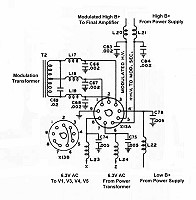
Click On A Section of the Schematic
Below for Information on That Part of the Circuit:
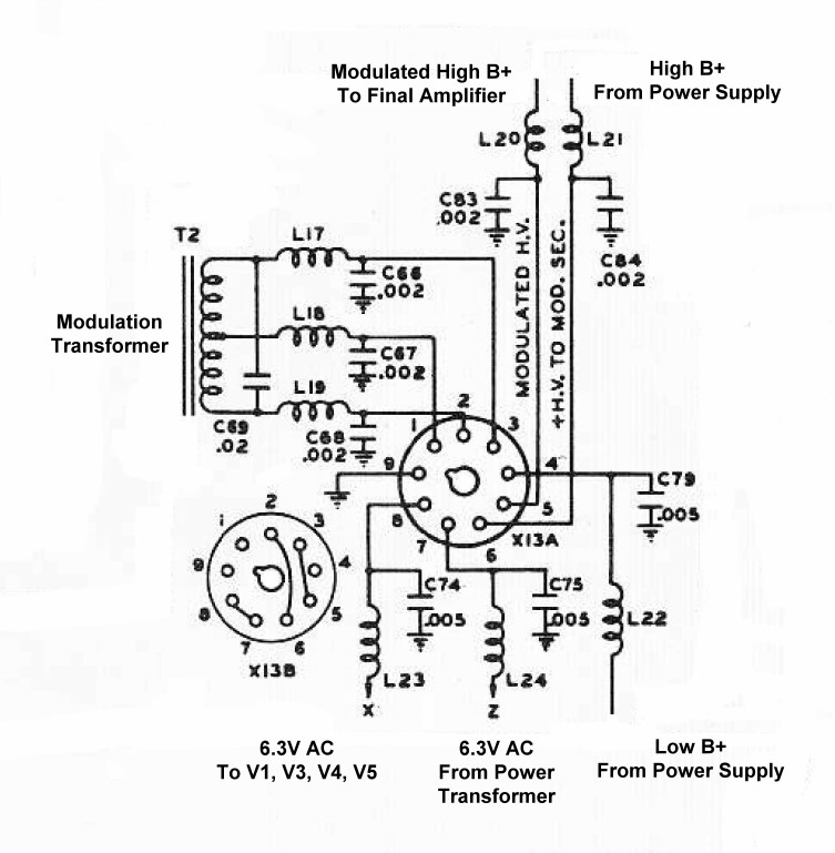
| Modulation Transformer: The modulation transformer matches the output of the modulator to the final RF amplifier. The transformer turns ratio is selected so that when the modulator is delivering enough power for 100% modulation (32.5 watts) the peak positive voltage in the secondary is exactly equal to the output of the high B+ supply (about 500 volts). Under such conditions, the instantaneous voltage on the final RF amplifier will swing at an audio rate from 0 volts to 1000 volts (twice the high B+ voltage). |
 |
| High B+ From Power Supply: High B+ of approximately 500V DC is available from pin 6 of the accessory socket. This pin is normally connected through a jumper on the 9-pin accessory plug to pin 2 and the modulation transformer secondary. |
 |
| 6.3V AC To V1, V3, V4, and V5 Filaments: Pin 8 supplies 6.3V AC to the filaments of V1, V3, V4, and V5. It is normally connected to pin 7 through a jumper on the 9-pin accessory plug. If the plug is not inserted, or if the jumper is absent, V1, V3, V4, and V5 will not operate and the RF circuits will be disabled. This feature can be used to disable the RF circuits when the Ranger is being used as a PA amplifier or power supply. |
 |
| Low B+ From Power Supply: Low B+ of approximately 300V DC is available from pin 4 of the accessory socket. |
 |
 Back to Dr.
Greg Latta's Electrical Engineering and Amateur Radio Pages
Back to Dr.
Greg Latta's Electrical Engineering and Amateur Radio Pages
 If you have any questions or
comments, you can send E-Mail to Dr. Greg Latta at
glatta@frostburg.edu
If you have any questions or
comments, you can send E-Mail to Dr. Greg Latta at
glatta@frostburg.edu