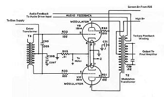
Click here for a higher resolution (larger) schematic.

Introduction:
The modulator is an audio power amplifier that modulates the final RF
amplifier. The output of the modulator is in series with the high B+ lead to
the final RF amplifier, and thus controls the instantaneous plate voltage on
the final amplifier. At 100% modulation the instantaneous plate voltage varies
from 0 volts to 1000 volts (twice the high B+ voltage) at an audio rate.
To fully modulate an RF power amplifier requires an audio power output equal to
1/2 of the DC input of the final stage. Rated input for the Ranger is 65 watts,
so a minimum of 32.5 watts of audio is needed. The modulator in the Ranger is
able to supply almost 50 watts when 6L6GC tubes are used, so the modulator has
plenty of reserve to do the job.
The modulator uses a push-pull circuit with fixed bias and and features a
tertiary feedback winding to lower distortion
and smooth out response. Metering of the cathode current is provided, and the
screen voltage can be
adjusted with R35 to obtain the proper resting current.
Modulator
Circuit
Click On A Section of the Schematic
Below for Information on That Part of the Circuit:
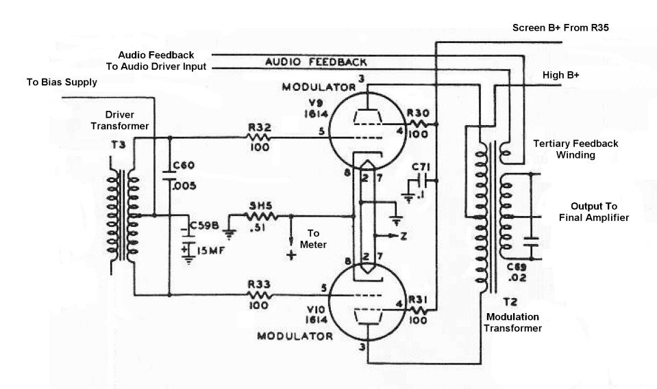
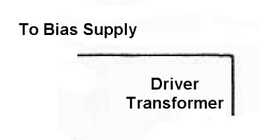
| Bias Input: Fixed bias is applied to the the modulator tubes through the audio driver transformer center tap. The bias voltage is obtained from a full wave bias supply that also supplies negative voltage to the keying circuit. The bias rises slightly during key up conditions, lowering the idle current and thus the heating in the in the modulator tubes during receive periods. |
 |
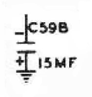
| Bias Isolation Capacitor: The center tap of the audio driver transformer must be at ground potential for audio frequencies. Capacitor C59B grounds the center tap for audio frequencies, but prevents the negative DC bias from being short circuited to ground. |
 |
| Audio Driver Transformer: The output of the audio driver tube is fed to the modulator through the audio driver transformer. The transformer matches the output impedance of the audio driver tube to the input impedance of the modulator. Since the modulator tubes must be driven out of phase, the transformer secondary is center tapped. The center tap is grounded for audio frequencies by capacitor C59B. The modulator tube grids are connected to opposite ends of the secondary, which are out of phase with each other. |
 |
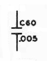
| First High Frequency Cut Capacitor: To limit the bandwidth of the audio system and to help stabilize the system, capacitor C60 is connected across the audio driver transformer secondary. This shorts out some of the higher frequencies, preventing them from reaching the grids of the modulator tubes. |
 |
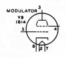
| 1614/6L6GC Modulator Tube: 1614 tubes were originally used for the modulator tubes in the Ranger transmitter. The 1614 is essentially a 6L6 rated for RF transmitter service, though it works fine at audio frequencies. Why the Johnson engineers chose to use a more expensive RF tube for audio frequencies is probably just a sales gimmick, because the regular metal 6L6 would have worked just as well. Or perhaps they got a deal when purchasing the tubes. It is hard to say. Modern glass 6L6GC tubes should be used if the 1614 tubes need to be replaced. The 6L6GC tubes have a much higher plate dissipation rating and thus run very conservatively when used as modulators in the Ranger transmitter. You can click here for a 6L6GC data sheet or a 1614 data sheet. |
 |
| Screen B+ From R35: Screen voltage for the modulator tubes is obtained through an adjustable voltage divider resistor (R35) from the high B+ power supply. The divider resistor also supplies current to the screen grid of the clamper tube. During key up periods the screen voltage drops slightly due to the extra current drawn by the clamper tube. This lowers modulator idle current during key up periods. Click here to read how to properly adjust R35. |

|
| Modulation Transformer: The modulation transformer matches the output of the modulator to the final RF amplifier. The transformer turns ratio is selected so that when the modulator is delivering enough power for 100% modulation (32.5 watts) the peak positive voltage in the secondary is exactly equal to the output of the high B+ supply (about 500 volts). Under such conditions, the instantaneous voltage on the final RF amplifier will swing at an audio rate from 0 volts to 1000 volts (twice the high B+ voltage). The modulation transformer also contains a tertiary audio feedback winding to provide negative feedback and lower the overall distortion of the audio driver/modulator system. |
 |
| Audio Feedback Winding: The tertiary audio feedback winding on the modulation transformer is one of the most important parts of the Ranger audio system. This winding picks up the same signal as the modulation transformer secondary, but at a lower voltage. This signal is fed out of phase back into the input of the audio driver. This negative feedback slightly lowers the overall gain of the audio driver/modulator combination, but also cancels out most of the distortion produced by the system, improves the frequency response, and helps to stabilize the system and prevent spurious oscillations. An additional winding on the modulation transformer raises the cost, but the improvement in performance is well worth the expense. It is one of the reasons that the Viking Ranger is such a good sounding transmitter. |
 |
 Back to Dr.
Greg Latta's Electrical Engineering and Amateur Radio Pages
 If you have any questions or
comments, you can send E-Mail to Dr. Greg Latta at
glatta@frostburg.edu