Click here for a higher resolution (larger) schematic.
Introduction:
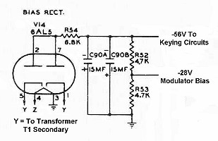
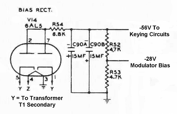
The bias power supply provides the negative bias for the grid block keying
circuits and the modulator. Very little current is required, but the output of
the supply must be very clean and hum free. The supply uses two taps
("Y") on the power transformer in a classic full wave center tapped
configuration.
Because the supply is positive ground, the rectifier tube cannot have a common
cathode. The 6AL5 7-pin dual diode has two totally independent diodes and is
perfect for this low voltage/low current application. The supply uses a
capacitor input filter and the output is fed to the
keying circuit and, after passing
through a voltage divider, to the modulator circuit.
Bias/Keying Power
Supply
Click On A Section of the Schematic
Below for Information on That Part of the Circuit:
| 6AL5 Rectifier Tube |
| Power Transformer T1 Secondary |
| Voltage Dropping Resistor |
| Filter Capacitors |
| Modulator Voltage Divider |
| 6AL5 Rectifier Tube: The bias supply has a positive ground, and this means that the rectifier tube cannot have a common cathode, A rectifier with separate cathodes must be used. However, the output current and voltage of the bias supply are relatively low. The 6AL5 is a small 7-pin tube with two completely independent diodes and is ideally suited for this application. You can click here for a 6AL5 data sheet. |

|
 Back to Dr.
Greg Latta's Electrical Engineering and Amateur Radio Pages
Back to Dr.
Greg Latta's Electrical Engineering and Amateur Radio Pages
 If you have any questions or
comments, you can send E-Mail to Dr. Greg Latta at
glatta@frostburg.edu
If you have any questions or
comments, you can send E-Mail to Dr. Greg Latta at
glatta@frostburg.edu


