Click here for a higher resolution (larger) schematic.
Introduction:
The clamper circuit protects the
final amplifier tube
when a signal is not present at the input to the amplifier, for example, during
key up periods. The circuit samples the bias on the final amplifier tube, and
if the bias is absent it lowers the screen voltage on the final amplifier to a
safe value, protecting the screen grid and plate of the final amplifier tube.
Clamper
Circuit
Click On A Section of the Schematic
Below for Information on That Part of the Circuit:

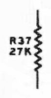
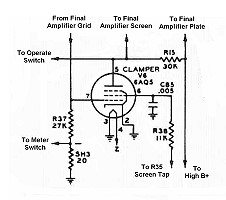
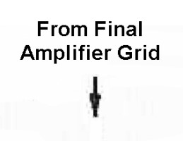
| Input From Final Amplifier Grid: The grid of the final amplifier tube is connected through an RF choke to the grid leak resistor R37. Grid current through the grid leak resistor develops grid leak bias, which is also applied to the grid of the clamper tube. When the grid leak bias is present, the clamper tube is cutoff and draws no additional current through the final screen dropping resistor. |
 |
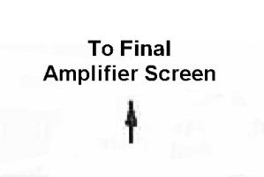
| Connection To Final Amplifier Screen Grid: The plate of the clamper tube is connected to the screen grid of the final amplifier tube. When grid leak bias is present on the final amplifier, indicating that a signal is present, the clamper tube is cutoff and has no effect. However, if grid leak bias is absent, the clamper tube turns on and pulls extra current through the final amplifier screen dropping resistor, increasing the voltage drop across the resistor. This lowers the screen voltage far below its normal value and protects the final amplifier tube from excessive current. |
 |
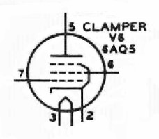
| 6AQ5 Tube: The clamper tube V6 is either cutoff or fully on. When turned on it must be able to draw enough current through the final screen dropping resistor to lower the final screen voltage to a safe value during zero signal conditions. The plate dissipation of the tube must be high enough to handle the heat produced when the tube is turned on. The 6AQ5 is an inexpensive 7-pin beam power tube with a plate dissipation of 12 watts. It can easily handle the necessary current and heat when turned on and its relatively high transconductance means that it can be easily cutoff. It is ideal for this application. You can click here for a 6AQ5 data sheet. |
|
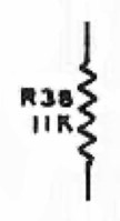
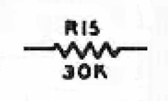
| Final Amplifier Screen Dropping Resistor: The screen voltage for the 6146 is obtained from the high B+ supply through dropping resistor R15. This resistor is chosen so that the screen voltage is the proper value when the final amplifier tube is drawing rated screen current. The value of this resistor is fairly critical, since the screen voltage has a big effect on the operation of the amplifier. When a signal is absent from the input of the final amplifier, as during key up periods in CW mode, the clamper tube turns on and pulls extra current through the dropping resistor, increasing the voltage drop across the resistor, lowering the screen voltage far below its normal value. This protects the final amplifier tube from excessive current. This resistor must have a power rating sufficient to take the entire high B+ supply since it is connected directly across the high B+ supply when the Operate Switch is in "Standby" mode. |
 |
| Connection To High B+: The high B+ power supply provides the plate voltages for the final amplifier and the modulator tubes. The screen voltage for the final amplifier tube and is obtained from the high B+ through final amplifier screen dropping resistor R15. The screen voltages for the modulator tubes and the clamper tube are obtained from the high B+ supply through voltage divider/bleeder resistor R35. |
 |
 Back to Dr.
Greg Latta's Electrical Engineering and Amateur Radio Pages
Back to Dr.
Greg Latta's Electrical Engineering and Amateur Radio Pages
 If you have any questions or
comments, you can send E-Mail to Dr. Greg Latta at
glatta@frostburg.edu
If you have any questions or
comments, you can send E-Mail to Dr. Greg Latta at
glatta@frostburg.edu