
Click here for a higher resolution (larger) schematic.
Introduction:
The Johnson Viking Ranger uses the venerable 6146 tube for the final amplifier.
The tube is operated under very conservative CCS conditions in the Ranger, with
a recommended output about 45W in CW mode and 40W carrier in AM mode. A
clamper tube is used to lower the
screen voltage and protect the final amplifier during key up conditions.
Final
Amplifier
Click On A Section of the Schematic
Below for Information on That Part of the Circuit:
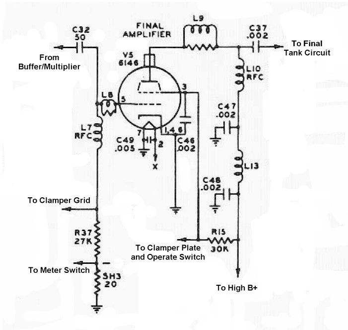
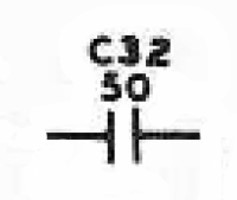
| Input Coupling Capacitor: The signal from the buffer/multiplier passes to the grid of the final amplifier through the input coupling capacitor C32. This capacitor also functions as the plate coupling capacitor for the buffer/multiplier stage. The capacitor allows the RF to flow through while blocking the DC on the plate of the buffer/multiplier tube. |
 |
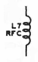
| Grid RF Choke: The grid bias developed during operation of the final amplifier must be applied to the grid of the clamper tube, and the grid current must pass through the grid metering resistor for proper metering of the grid current. However, no RF must be allowed to leave the grid of the final amplifier tube. The grid RF choke L7 allows direct current to pass through, while blocking the passage of any any RF. |
 |
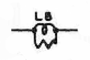
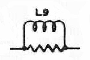
| Grid Parasitic Suppressor: Stray coupling can cause the final amplifier to take off and oscillate on its own on VHF frequencies. Parasitic suppressors such as L8 and L9 load the circuit on these frequencies, suppressing the undesired oscillations. They typically consist of a small coil wound directly on the body of a resistor. |
 |
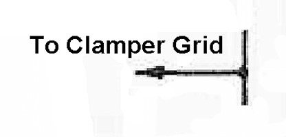
| Output To Clamper Tube: Operating bias for the final amplifier tube is obtained exclusively from grid leak bias. If no input signal is present (as when the key is up in CW), the grid bias is zero and the tube will draw excessive plate current, ruining the tube. This connection runs to the grid of the clamper tube. The clamper tube monitors the final amplifier grid bias and if it detects that the bias is absent, it lowers the screen voltage on the final amplifier tube, protecting the tube. |
 |
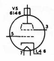
| 6146 Tube: The 6146 and its various descendents (6146A, 6146B) was and still is one of the most popular transmitting tubes in amateur radio service. The tube was originally introduced by RCA in an ad in the January, 1952 issue of QST magazine. The tube features a shielded base and a triple connection to the cathode, which greatly improves the performance and stability of the tube, allowing it to be used at frequencies up to 175MHz. With an ICAS plate dissipation of 25 watts a single 6146 can produce a maximum output on CW of 69 watts while operating with a plate voltage of only 750 volts. This is remarkable compared to other tubes available in the 1950s, which require higher plate voltages and/or higher driving power for the same output. The plate voltage on the 6146 in the Johnson Viking Ranger is a conservative 500V. Under class C service and with 500V on the plate, a single 6146 can produce 48W of output when running CW. When run on AM under the same conditions, a carrier output of approximately 40W can be obtained. These are CCS (Continuous Commercial Service) conditions, rather than ICAS (Intermittent Commercial and Amateur Service) conditions. CCS conditions are very conservative compared to ICAS conditions and a tube operated under such conditions by an amateur radio operator should give very long and reliable service. You can click here for a copy of the 6146 data sheet in .pdf format. |
|
| Clamper Plate And Operate Switch: For the clamper circuit to operate properly, the plate of the clamper tube must be connected to the screen grid of the final amplifier tube. When the clamper tube turns on, it lowers the screen voltage on the final amplifier tube, protecting the tube from excessive current. The "Operate" switch is also connected to the screen grid of the tube, and grounds the screen grid in "Standby" mode, disabling the final amplifier. |
 |
| Screen Dropping Resistor: The screen voltage for the 6146 is obtained from the high B+ supply through dropping resistor R15. This resistor is chosen so that the screen voltage is the proper value when the tube is drawing rated current. The value of this resistor is fairly critical, since the screen voltage has a big effect on the operation of the amplifier. The screen dropping resistor is also closely tied to the operation of the clamper circuit. When a signal is absent from the input of the final amplifier, as during key up periods in CW mode, the clamper tube pulls extra current through the dropping resistor, lowering the screen voltage far below its normal value, and protecting the final amplifier tube from excessive current. |
 |
| Plate Parasitic Suppressor: Stray coupling can cause the final amplifier to take off and oscillate on its own on VHF frequencies. Parasitic suppressors such as L9 and L8 load the circuit on these frequencies, suppressing the undesired oscillations. They typically consist of a small coil wound directly on the body of a resistor. |
 |
| Plate RF Chokes: The plate RF chokes L10 and L13 prevent any RF from getting back into high B+ supply while allowing the DC current to reach the plate of the final amplifier tube. Since a lot of RF is present at the plate of the final amplifier tube, two RF chokes and two plate bypass capacitors are used to make sure that no RF gets into the high B+ power supply or any other place it shouldn't. |
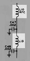 |
| Plate Bypass Capacitors: The plate bypass capacitors C47 and C48 bypass any RF that may have leaked through the plate RF chokes to ground, preventing the RF from reaching the high B+ power supply. Two capacitors are used because of the high amount of RF present on the plate of the final amplifier tube. |
 |
| Plate Coupling Capacitor: RF appearing at the plate of the final amplifier tube must be fed to output tank circuit, but the DC plate voltage must not be allowed to pass through. The plate coupling capacitor C37 allows the RF to pass through while blocking the DC. This capacitor must be able to handle much more than just the nominal DC plate voltage (500V) on the final amplifier tube. With 100% modulation, the peak voltage on the plate of the final amplifier tube is 4 times the DC plate voltage, or 2000V, so this capacitor must be rated for at least 2000V. |
 |
 Back to Dr.
Greg Latta's Electrical Engineering and Amateur Radio Pages
Back to Dr.
Greg Latta's Electrical Engineering and Amateur Radio Pages
 If you have any questions or
comments, you can send E-Mail to Dr. Greg Latta at
glatta@frostburg.edu
If you have any questions or
comments, you can send E-Mail to Dr. Greg Latta at
glatta@frostburg.edu


