Click here for a higher resolution (larger) schematic.
Introduction:
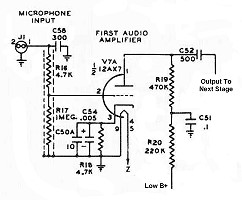
The first audio amplifier takes the signal from the microphone and amplifies it
by about 35dB. The first audio amplifier always operates at maximum gain to
minimize noise. Component values (particularly C52) are chosen to limit the frequency response and
improve the communications effectiveness of the transmitted signal. A
second audio amplifier
amplifies the signal by an additional amount of up to 35db for a total maximum
of about 70dB.
First Audio
Amplifier Circuit
Click On A Section of the Schematic
Below for Information on That Part of the Circuit:

| Grid Resistor: The grid resistor R17 provides a load for the microphone and allows the DC bias developed by the cathode bias resistor to pass through to the grid of the tube. |
 |
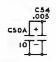
| Cathode Bypass Capacitors: Without the cathode bypass capacitors, the voltage developed by the cathode bias resistor would fluctuate with the varying plate current and produce negative feedback, lowering the gain of the stage. The cathode bypass capacitors C50A and C54 smooth out the variations and provide a steady bias for the tube. Another way to look at it is that the plate/cathode current contains both a DC component and an AC component (the output signal). The bypass capacitors shunt the AC component around the cathode bias resistor so that only the DC component contributes to the cathode bias. To make sure that any stray RF in the transmitter doesn't affect the bias, two capacitors are used in parallel. C50A is the main audio bypass capacitor. However, electrolytic capacitors such as C50A can have high stray inductance and not function well at radio frequencies. To insure that the cathode bias resistor is also bypassed for RF, C54 is placed in parallel with C50A. Whatever isn't bypassed by C50A is then bypassed by C54. |
 |
| Cathode Bias Resistor: The grid of the tube must be kept negative to operate properly. Plate/cathode current flowing through the cathode bias resistor produces a voltage that is applied through the grid resistor to the grid of the tube. Variations in this voltage are smoothed out by the cathode bypass capacitors to provide a steady grid bias on the tube. |
 |
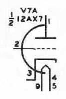
| 12AX7A Tube: The 12AX7A is the most common tube used in audio preamplifiers. It is used in just about every hi-fi tube preamplifier or guitar amplifier. It features low noise and high voltage gain. The typical gain for a single 12AX7A section is 35dB. Two sections in cascade (a single tube) can thus provide a total average gain of 70dB. You can click here for a 12AX7A data sheet. |
|
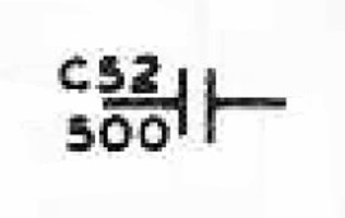
| Interstage Coupling Capacitor: Interstage coupling capacitor C52 couples the audio output of the first audio amplifier to the input of the second audio amplifier, while preventing the plate voltage on the first audio amplifier from getting through. The reactance of this capacitor is quite high at the lower audio frequencies. For example, the reactance is about 1Mohm at 300Hz. This is done intentionally to lower the response at the lower audio frequencies. Keeping the response down at the lower audio frequencies leaves more room for the mid and high frequencies, and improves the overall communications effectiveness of the final transmitter signal. For some hams, better audio fidelity is preferred over communications effectiveness. To increase the bass response, this capacitor can be increased in value to about 0.01uf. You can read about this modification here . |
 |
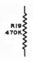
| Load Resistor: When the tube draws current through load resistor R19, it produces a voltage drop across the resistor. The instantaneous voltage on the plate of the tube is the difference between the supply voltage and the drop across the plate load resistor. Thus, when the tube draws more current, the plate voltage drops, and vice versa. The varying tube current thus produces a varying plate voltage, which is passed on to the next stage through the plate/interstage coupling capacitor. |
 |
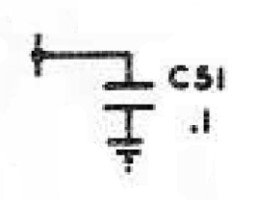
| Decoupling Capacitor: The varying current drawn by the tube can cause a slight variation in the low B+ supply voltage, which can undesirably affect other stages operating from the low B+ supply. Decoupling capacitor C51 and decoupling resistor R20 smooth out these variations, preventing them from affecting the low B+ supply voltage and affecting other stages. |
 |
| Decoupling Resistor: The varying current drawn by the tube can cause a slight variation in the low B+ supply voltage, which can undesirably affect other stages operating from the low B+ supply. Decoupling resistor R20 and decoupling capacitor C51 smooth out these variations, preventing them from affecting the low B+ supply voltage and affecting other stages. |
 |
 Back to Dr.
Greg Latta's Electrical Engineering and Amateur Radio Pages
Back to Dr.
Greg Latta's Electrical Engineering and Amateur Radio Pages
 If you have any questions or
comments, you can send E-Mail to Dr. Greg Latta at
glatta@frostburg.edu
If you have any questions or
comments, you can send E-Mail to Dr. Greg Latta at
glatta@frostburg.edu

