
Click here for a higher resolution (larger) schematic.
Introduction:
The second audio amplifier takes the signal from the
first audio amplifier and
amplifies it by as much as 35dB. The gain of the second audio amplifier is
controlled by the front panel "Audio" control. Component values
(particularly C52, C53, and C56) are chosen to
limit the frequency response and improve the communications effectiveness of
the transmitted signal. The output of the second audio amplifier is fed to the
audio driver circuit.
Second Audio
Amplifier Circuit
Click On A Section of the Schematic
Below for Information on That Part of the Circuit:
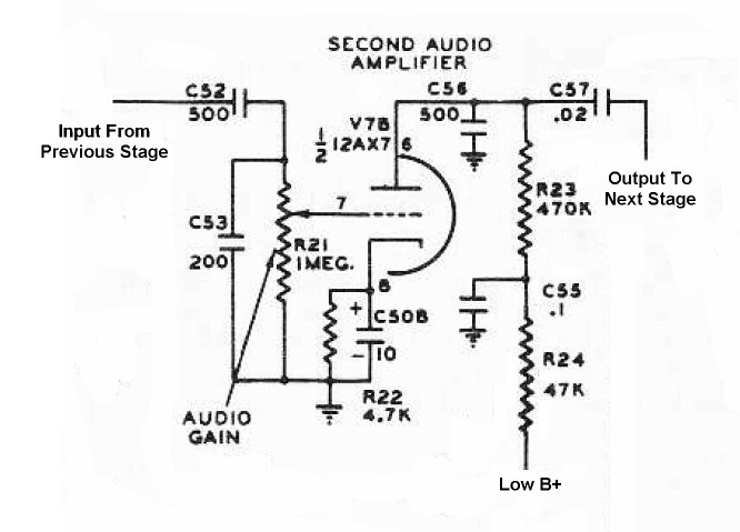
| Input Coupling Capacitor: Input coupling capacitor C52 couples the audio output of the first audio amplifier to the input of the second audio amplifier, while preventing the plate voltage on the first audio amplifier from getting through. The reactance of this capacitor is quite high at the lower audio frequencies. For example, the reactance is about 1Mohm at 300Hz. This is done intentionally to lower the response at the lower audio frequencies. Keeping the response down at the lower audio frequencies leaves more room for the mid and high frequencies, and improves the overall communications effectiveness of the final transmitter signal. For some hams, better audio fidelity is preferred over communications effectiveness. To increase the bass response, this capacitor can be increased in value to about 0.01uf. You can read about this modification here . |
 |
| First High Cut Capacitor: The bandwidth of an AM signal is equal to twice the highest modulating frequency. To prevent excessive bandwidth and to improve intelligability, it is important to limit the high frequency response of the audio system. First high cut capacitor C53 shunts some of the audio around the audio gain control, shorting it to ground. Since the reactance of the capacitor decreases as the frequency increases, the amount of signal shunted to ground increases as the frequency goes up. The effect is to decrease the gain of the stage with increasing frequency, creating a high frequency roll off that limits the bandwidth of the transmitted signal. Both the first high cut capacitor and the second high cut capacitor contribute to the overall high frequency roll off of the audio system. Both capacitor values are carefully chosen to produce the desired roll off. |
 |
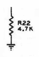
| Audio Gain Control/Grid Resistor: Audio gain control R21 functions as a voltage divider on the incoming signal. A fraction of the signal passing through the input coupling capacitor is applied to the grid of the second audio tube, depending on the setting of the front panel "Audio" control. The audio gain control also functions as a grid resistor by allowing the DC bias developed by the cathode bias resistor to pass through to the grid of the tube. |
 |
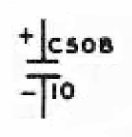
| Cathode Bypass Capacitor: Without the cathode bypass capacitor, the voltage developed by the cathode bias resistor would fluctuate with the varying plate current and produce negative feedback, lowering the gain of the stage. The cathode bypass capacitor C50B smooths out the variations and provides a steady bias for the tube. Another way to look at it is that the plate/cathode current contains both a DC component and an AC component (the output signal). The bypass capacitor shunts the AC component around the cathode bias resistor so that only the DC component contributes to the cathode bias. |
 |
| Cathode Bias Resistor: The grid of the tube must be kept negative to operate properly. Plate/cathode current flowing through the cathode bias resistor produces a voltage that is applied through the audio gain control/grid resistor to the grid of the tube. Variations in this voltage are smoothed out by the cathode bypass capacitor to provide a steady grid bias on the tube. |
 |
| 12AX7A Tube: The 12AX7A is the most common tube used in audio preamplifiers. It is used in just about every hi-fi tube preamplifier or guitar amplifier. It features low noise and high voltage gain. The typical gain for a single 12AX7A section is 35dB. Two sections in cascade (a single tube) can thus provide a total average gain of 70dB. You can click here for a 12AX7A data sheet. |
 |
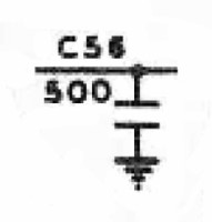
| Second High Cut Capacitor: The bandwidth of an AM signal is equal to twice the highest modulating frequency. To prevent excessive bandwidth and to improve intelligability, it is important to limit the high frequency response of the audio system. Second high cut capacitor C56 shunts some of the audio coming out of tube directly to ground. Since the reactance of the capacitor decreases as the frequency increases, the amount of signal shunted to ground increases as the frequency goes up. The effect is to decrease the gain of the stage with increasing frequency, creating a high frequency roll off that limits the bandwidth of the transmitted signal. Both the second high cut capacitor and the first high cut capacitor contribute to the overall high frequency roll off of the audio system. Both capacitor values are carefully chosen to produce the desired roll off. |
 |
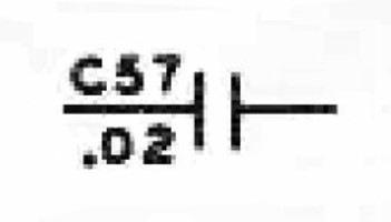
| Output Coupling Capacitor: Output coupling capacitor C57 couples the audio output of the second audio amplifier to the input of the audio driver stage, while preventing the plate voltage on the second audio amplifier from getting through. |
 |
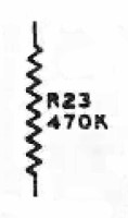
| Load Resistor: When the tube draws current through load resistor R23, it produces a voltage drop across the resistor. The instantaneous voltage on the plate of the tube is the difference between the supply voltage and the drop across the plate load resistor. Thus, when the tube draws more current, the plate voltage drops, and vice versa. The varying tube current thus produces a varying plate voltage, which is passed on to the next stage through the output coupling capacitor. |
 |
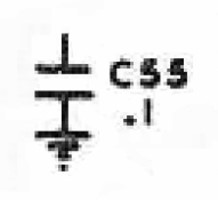
| Decoupling Capacitor: The varying current drawn by the tube can cause a slight variation in the low B+ supply voltage, which can undesirably affect other stages operating from the low B+ supply. Decoupling capacitor C55 and decoupling resistor R24 smooth out these variations, preventing them from affecting the low B+ supply voltage and affecting other stages. |
 |
| Decoupling Resistor: The varying current drawn by the tube can cause a slight variation in the low B+ supply voltage, which can undesirably affect other stages operating from the low B+ supply. Decoupling resistor R24 and decoupling capacitor C55 smooth out these variations, preventing them from affecting the low B+ supply voltage and affecting other stages. |
 |
 Back to Dr.
Greg Latta's Electrical Engineering and Amateur Radio Pages
Back to Dr.
Greg Latta's Electrical Engineering and Amateur Radio Pages
 If you have any questions or
comments, you can send E-Mail to Dr. Greg Latta at
glatta@frostburg.edu
If you have any questions or
comments, you can send E-Mail to Dr. Greg Latta at
glatta@frostburg.edu