Remote Control
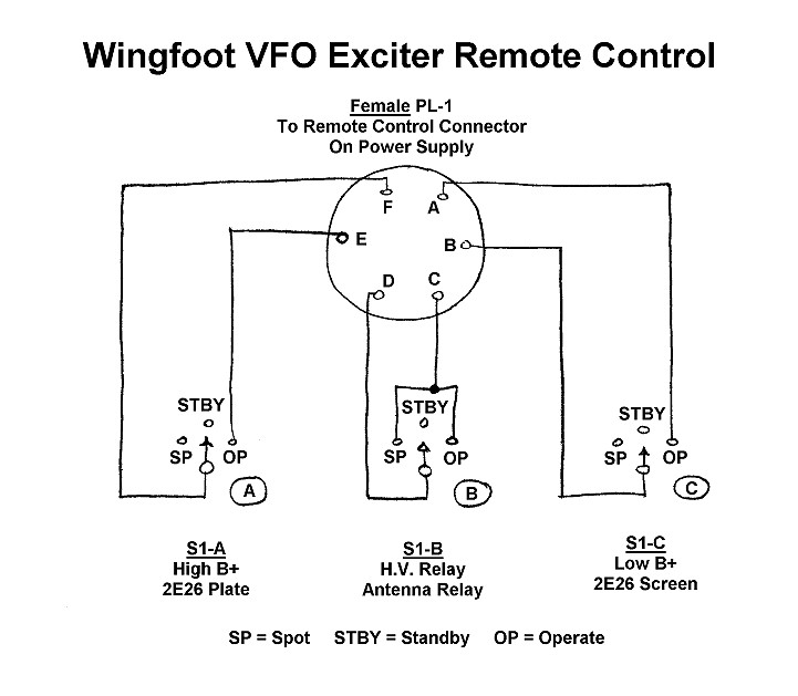
General Information: The operation of the remote control is
straightforward. The Mode Switch is a 3-pole, 3-position ceramic wafer switch
that places the transmitter in three modes: Spot, Standby, and Operate. Each
section/pole of the switch is connected via a shielded cable to a pair of pins
on the power
supply remote control connector. Pins A, C, and E feed low B+, 117V AC, and
high B+ respectively from the power supply to the three sections of the mode
switch. Pins B, D, and F carry these voltages back to the power supply after
they have travelled trhough the switch.
Spot Mode: When the switch is placed in the "Spot" position,
only pins C and D are shorted together. This activates the high voltage
relay coil in the
power supply, turning on the low B+ and high B+ power supplies. It also places
117V AC on the power supply
antenna relay connector, activating any device attached to the connector,
such as an antenna changeover relay. In this mode all sections of the
transmitter except the final amplifier are enabled. This allows the operator to
key the transmitter and tune the receiver and transmitter to the same
frequency, which is known as "spotting" the transmitter.
Standby Mode: When the switch is in the Standby position, all switches
are open and the low B+, 117V AC, and high B+ voltages go nowhere. Only the
filament and bias voltages are applied to the transmitter, and it is standby
mode.
Operate Mode: When the switch is placed in the "Operate"
position, pins A and B, C and D, and E and F are shorted together.
a. Shorting pins E and F together places high B+ on pin F of the
power supply
output connector, applying high B+ to the plate of the
final amplifier.
b. Shorting pins C and D together activates the high voltage
relay coil in the
power supply, turning on the low B+ and high B+ power supplies. It also places
117V AC on the power supply
antenna relay connector, activating any device attached to the connector,
such as an antenna changeover relay.
c. Shorting pins A and B together places low B+ on pin B of the
power supply
output connector, turning on the final amplifier
screen regulator.
In "Operate" mode the entire transmitter, including the final
amplifier, is enabled.
 Back to Dr.
Greg Latta's Electrical Engineering and Amateur Radio Pages
Back to Dr.
Greg Latta's Electrical Engineering and Amateur Radio Pages
 If you have any questions or
comments, you can send E-Mail to Dr. Greg Latta at
glatta@frostburg.edu
If you have any questions or
comments, you can send E-Mail to Dr. Greg Latta at
glatta@frostburg.edu