Click On A Section of the Schematic
Below for Information on That Part of the Circuit:
General Information On The Plate Power Supply:
The plate power supply provides the filament, low B+, and high B+ voltages for
the Wingfoot VFO Exciter. The low B+
supply is used to power all of the stages in the exciter except for the final
amplifier plate, which is powered by the high B+ supply.
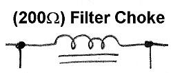
Both B+ supplies have good regulation due to the use of filter chokes. The regulation of the low B+ supply from key up to key down is about 7%. The regulation of the high B+ supply from key up to key down is about 12%. Output of the low B+ supply key down is about 430V, and the output of the high B+ supply key down is about 790V. For critical circuits like the oscillator, and 1st and 2nd buffers, a source of regulated voltage is also available.
Excessively High Plate Voltages:
The original builder, Jim Trutko,
W8EXI, used the power transformer he had on hand, which was a TV
transformer with a 750V secondary. As a result, the low B+ and high B+ voltages
under key up conditions are 462V and 877V respectively. These greatly exceed
the recommended maximum plate and screen voltages for the 6AG7 and 2E26 tubes
used in the Wingfoot VFO Exciter. If the screens of all of the tubes were
powered by dropping resistors from the B+ plate supplies (as is typical), under
key up conditions the screen voltages would rise to the full, unloaded B+
voltages. This would cause arcing between the screen grids and control grids,
ruining the tubes or, if the arcing didn't occur, the high screen voltages
would prevent the grid-block keying voltage from cutting off the tubes, and
they would quickly overheat. Either way, the tubes would be ruined.
However, the plate of the oscillator tube is regulated at 258V and the screens of all of the 6AG7 tubes are regulated at 150V by the power supply voltage regulator circuit. In addition, the screen of the final amplifier tube is fed from an adjustable screen voltage regulator, which typically keeps the final amplifier screen grid at about 120V. Since the screen grids are all regulated, the problems listed in the previous paragraph do not occur. It is true that the plate voltages on the tubes are above their recommended maximum values, but this causes no problems because the plates are designed to handle peak voltages much higher than the DC operating voltage placed on the tubes.
The use of regulated screen voltage on the tubes with higher than normal plate voltages has proven successful since there have been no problems in the 15+ years I have been using the Wingfoot VFO transmitter, and I have yet to replace any of the tubes. I have, however, been careful to limit the output of the transmitter to the 27 watts listed as the maximum for the 2E26 final amplifier tube, even though the transmitter can put out considerably more.
Plate Power Supply
Click On A Section of the Schematic
Below for Information on That Part of the Circuit:
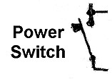
| Power Switch: The power supply switch is a standard SPST toggle switch. |
 |
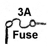
| Fuse: A 3 ampere fuse protects the power supply in the event of a failure. The fuse is mounted in a holder on the top of the power supply near the pilot lamp. |
 |
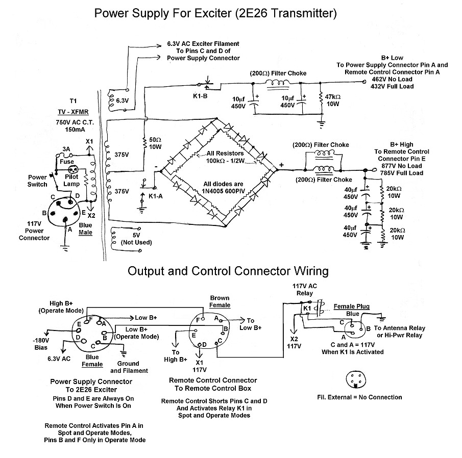
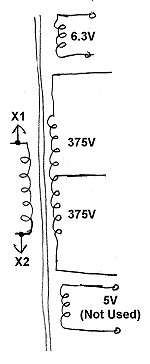
| Power Transformer: The power transformer is a heavy duty television transformer. These were available at very reasonable prices in the 1950s and 1960s. One could buy a replacement unit, or, if lucky, one could be obtained from a worn out television set. The transformer has more than enough output for the transmitter power supply. Televisions used many more tubes than the transmitter, so the 6.3V filament winding has more than enough current capability. The 750V high voltage winding is high for this application, as explained at the top of this page, but the use of regulated screen voltages on all of the transmitter tubes solved this problem. The 5V filament winding, originally for the filament of a rectifier tube, is not used, allowing a little more power than normal to be drawn from the other windings if necessary. |
 |
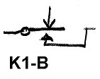
| Relay A: Relay K1 is a double pole relay specially designed for high voltage service. The relay coil is controlled by a switch on the remote control. Section A of the relay controls the high B+ supply. The relay coil is de-energized when the remote control is in "Standby" mode. The negative side of the bridge rectifier is then disconnected, disabling the high B+ supply. When the remote control is placed in the "Spot" or "Operate" modes, the relay coil is energized, and section A of the relay connects the negative lead of the bridge rectifier to ground, turning on the high B+ supply. |
 |
| Relay B: Relay K1 is a double pole relay specially designed for high voltage service. The relay coil is controlled by a switch on the remote control. Section B of the relay controls the low B+ supply. The relay coil is de-energized when the remote control is in "Standby" mode. The center tap of the transformer is then disconnected, disabling the low B+ supply. When the remote control is placed in the "Spot" or "Operate" modes, the relay coil is energized, and section B of the relay connects the center tap of the transformer to the low B+ power supply filter, turning on the low B+ supply. |
 |
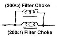
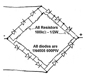
| Bridge Rectifier: The Wingfoot VFO power supply uses a full wave bridge rectifier and a center tapped transformer to provide two output voltages. To obtain a sufficient PIV rating in each leg of the rectifier, three diodes are strung in series with an equalizing resistor across each to make sure that the reverse voltage is split equally across each of the diodes. The entire bridge rectifier is connected across the entire transformer in a conventional full wave bridge circuit. The positive output is connected to the parallel chokes which are the input to the high B+ filter. The negative output is connected to ground when relay A is closed. The left two legs of the rectifier are used with the center tap of the transformer to form a conventional full wave center tapped rectifier. The only difference is that is this case the center tap of the transformer is the positive (rather than negative) output. The center tap is connected to the input of the low B+ filter when relay B is closed. This arrangement for obtaining two different output voltages from a single transformer and bridge rectifier is called the "Economy Power Supply" in the ARRL Handbook. This same arrangement is used in the 6146B amplifier power supply. |
 |
| Filter Capacitor: The low B+ supply uses a conventional capacitor input filter with a filter choke. The output of the rectifier is a stream of DC pulses at 120Hz that must be smoothed out. The filter capacitors store charge and smooth out the variations in the pulses. Another way to look at it is that the output of the rectifier is DC with a large AC component superimposed on it. The capacitors block the DC while short circuiting the AC to ground. |
 |
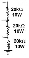
| Series Filter Capacitors: The filter capacitors pass AC while blocking DC, and effectively short any AC that has leaked through the parallel filter chokes to ground, eliminating it from the output. Filters capacitors with voltage ratings larger than 450V are expensive and/or impossible to find. To obtain the required voltage, three 40uf/450V capacitors are strung in series, yielding the equivalent of a single 13.3uf/1350V capacitor. Since the capacitors are low tolerance, and may have unequal values, equalizing resistors are connected across them to insure that the voltage is split equally across all three. |
 |
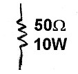
| Equalizing/Bleeder Resistors: Electrolytic capacitors are typically low tolerance, with the actual value differing substantially from the value marked on the capacitor. For the series filter capacitors, this means that the total voltage may not be split equally across the capacitors. The make sure that the voltage is split evenly across all three capacitors, equalizing resistors are connected across them to force the voltages to be the same. The resistors also provide a minimum load on the high B+ supply to make sure that the voltage doesn't soar to an excessively high value when the supply is lightly loaded. The resistors also discharge or "bleed" the capacitors when the supply is turned off so that a dangerous charge doesn't remain on the capacitors when the supply is turned off. |
 |
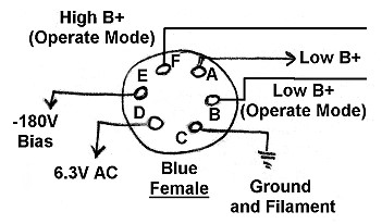
| Output Connector To Exciter: The output connector feeds power to the Wingfoot VFO Exciter. The low B+, filament, bias, and high B+ supplies all share pin C as a common ground. Filament and bias voltages are present at pins D and E as long as the power supply is turned on. Low B+ is present at pin A only when the remote control mode switch is placed in the "Spot" or "Operate" position. Pins B and F feed low B+ and high B+ to the final amplifier screen regulator and the final amplifier plate. Low B+ and high B+ are only present on pins B and F when the mode switch is in the "Operate" position. As a result of this switching scheme, filament and bias voltages are present at all times, keeping the transmitter in a state of readiness. When the mode switch is placed in the "Spot" position, the entire transmitter is enabled except for the final amplifier. This allows the operator to key the transmitter and tune the receiver and transmitter to the same frequency. When the mode switch is switched to "Operate", the final amplifier is also enabled. |
 |
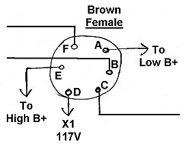
| Remote Control Connector: The remote control connector is used to connect the remote control to the transmitter. Pin A of the connector is connected to the output of the low B+ supply. Pin D is connected to the hot side of the 117V AC supply. Pin E is connected to the output of the high B+ supply. The remote control switch is a 3 pole 3 position switch mounted in the remote control. The three poles of the switch are connected to the pairs of pins A and B, C and D, and E and F. In the middle or "Standby" position these pairs of pins are all open. Low B+ does not appear at pin B, 117V AC does not appear on pin C, and high B+ does not appear at pin F. When the remote control switch is placed in the "Spot" position, pins C and D are shorted together, sending 117V AC to the relay coil and the antenna relay connector. The low B+ and high B+ power supplies are turned on and the external antenna relay, if connected, is activated. Pins A and B and E and F are still kept open. When the remote control switch is placed in the "Operate" position, pins C and D are shorted together, sending 117V AC to the relay coil and the antenna relay connector. The low B+ and high B+ power supplies are turned on and the external antenna relay, if connected, is activated. Pins A and B and E and F are also shorted to each other respectively, sending low B+ and high B+ to pins B and F of the output connector. |
 |
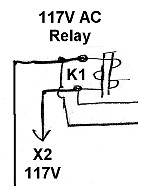
| Relay Coil: The relay coil is controlled by theremote control via the remote control connector. When the remote control is placed in the "Spot" or "Operate" position pins C and D of the remote control connector are shorted, connecting 117V AC to the relay coil and energizing the relay. relay contact A and relay contact B then turn on the high B+ supply and the low B+ supply. The 117V AC applied to the coil is also connected to the antenna relay connector where it can be used to control an external relay as well. |
|
| Antenna Relay Connector: The antenna relay connector is used to power an external relay, such as a transmit/receive antenna relay. When the mode switch on the remote control is placed in the "Spot" or "Operate" position, 117V AC is present at pins A and C to actuate the external relay. In practice, a heavy duty 15A relay is connected to the connector. The relay then controls a set of 4 117V AC outlets. The antenna transmit/receive relay is connected to one outlet, the Wingfoot 813 Amplifier power supply is connected to a second outlet, and a relay to control the T/R input to the Wingfoot 813 Amplifier or another amplifier is connected to a third. When the remote control is placed in "Spot" or "Operate" the following thus happen: 1. The antenna is switched form the receiver to the transmitter. 2. The Wingfoot 813 Amplifier power supply is turned on. 3. The Wingfoot 813 Amplifier (or another external amplifier) is switched to operate/transmit mode. |
 |
| External Filament Connector: An extra connector labeled "filament external" was originally intended to feed filament and low B+ voltages to a possible accessory, but it was never used. |
 |
 Back to Dr.
Greg Latta's Electrical Engineering and Amateur Radio Pages
Back to Dr.
Greg Latta's Electrical Engineering and Amateur Radio Pages
 If you have any questions or
comments, you can send E-Mail to Dr. Greg Latta at
glatta@frostburg.edu
If you have any questions or
comments, you can send E-Mail to Dr. Greg Latta at
glatta@frostburg.edu