Click On Any Section of the Schematic
Below for Information on That Part of the Circuit:
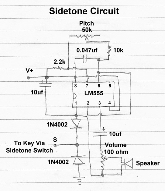
Sidetone Circuit:
The sidetone circuit uses a single 555 timer chip to provide a sidetone with
adjustable pitch and volume. The sidetone circuit runs on 9V to 12V DC and can
be connected across the key of any positive keyed transmitter. For use
with a negative keyed transmitter, it must be used with a
negative keying inverter. If
accidentally used without a keying inverter, the circuit will key the
transmitter, warning the operator of their error.
Sidetone Circuit
Click On Any Section of the Schematic
Below for Information on That Part of the Circuit:
Operation:
The circuit is a 555 timer chip connected as an audio oscillator. The circuit
is keyed by connecting and disconnecting the negative supply lead of the chip.
It can be used with any positive keyed transmitter. If it is
accidentally connected to a negative keyed transmitter, the lower protection
diode will key the transmitter, warning the operator of their error.
To Key Via Sidetone Switch:
The key is connected to the sidetone circuit via the
sidetone On/Off switch.
This allows the sidetone to be turned off if desired.
LM555 Integrated Circuit:
The LM555 or NE555 integrated circuit has many uses. Here it is used as an
audio oscillator (astable multivibrator).
50k Ohm Potentiometer, 10k Ohm Resistor, ans 0.047uf
Capacitor - Pitch Determining Components:
The pitch is determined by the setting of the pitch control, the 0.047uf
capacitor, and the 10k resistor. Decreasing the 10k resistor will raise the
maximum pitch. Decreasing the value of the capacitor will raise the pitch
overall. The values selected give a good range of pitch values.
100 Ohm Volume Control, 10uf Capacitor, and
Speaker:
The output of the LM555 is a series of positives pulses, essentially AC with an
added DC component. The 10uf coupling capacitor allows the AC to pass through
while blocking the DC component. The 100 ohm volume control functions as a
voltage divider to control the voltage applied to the speaker, and thus the
volume.
1N4002 Protective Diodes:
The diodes that are used here can be any of the 1N400X type, such as the
1N4002, 1N4007 etc. The upper diode prevents the positive voltage at the key
from flowing backwards into the LM555. The lower diode protects the circuit in
case the operator inadvertently connects the circuit to a negative keyed
transmitter. If the key input is accidentally connected to a negative keyed
transmitter, the lower diode will conduct and short the negative voltage to
ground. This protects the LM555 and keys the transmitter, warning the operator
of the problem.
V+ Positive Supply Voltage:
The sidetone generator requires a
positive voltage with
respect to ground for proper operation. This can be anywhere from 8V to 12V.
10uf Power Supply Bypass Capacitor:
The bypass capacitor filters out any noise or variations in the supply voltage,
keeping the circuit decoupled from the other circuits in the system.
 Back to Dr. Greg Latta's
Electrical Engineering and Amateur Radio Pages
Back to Dr. Greg Latta's
Electrical Engineering and Amateur Radio Pages
 If you have any questions or
comments, you can send E-Mail to Dr. Greg Latta at
glatta@frostburg.edu
If you have any questions or
comments, you can send E-Mail to Dr. Greg Latta at
glatta@frostburg.edu