Click On Any Section of the Schematic
Below for Information on That Part of the Circuit:
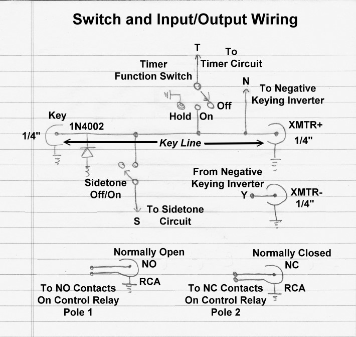
Switch and Input/Output Wiring:
There is one input to the T/R system, the 1/4" Key
Input on the front panel.
In addition to the 120V AC
Outlet, which can be used to control an antenna changeover relay, there are
four other outputs: XMTR+, XMTR-,
NO, and NC on the back panel.
These outputs are explained below.
In addition to the On/Off
switch on the front panel, there are two rotary switches on the top panel:
Sidetone and Timer. These two switches are explained below.
Switch and Input/Output
Wiring
Click On Any Section of the Schematic
Below for Information on That Part of the Circuit:
Operation:
There is one input to the T/R system, the 1/4"Key
input. This connects a key, keyer, or bug to the Key
Line.
In addition to the 120V AC
Outlet, which can be used to control an antenna changeover relay, there are
four other outputs: XMTR+, XMTR-,
NO, and NC on the back panel.
These outputs are explained below.
Two switches, the Sidetone Switch and the
Timer Switch connect and disconnect the
sidetone circuit and the
timer circuit to/from the
Key Line.
Key Line:
The key line is where the various circuits that must be keyed (negative keying inverter,
sidetone circuit) come
together. The line runs from the key input on the front panel directly to the
XMTR+ output on the back panel.
Key:
A key, keyer, or bug connects to this 1/4" input. The automatic CW T/R
system is designed to key a positive keyed transmitter, and presents a positive
key up voltage at the key input. If a negative keyed transmitter is plugged
into the XMTR+ output, a protection diode shunts it to ground, keying the
offending transmitter and warning the operator of their error.
Timer Function Switch:
The timer function switch has three positions. In the OFF position, the
timer circuit input is disconnected
from the key line and the timer is disabled. In the ON position the key line is
connected to the timer input and the timer is enabled. In the HOLD position the
timer input is disconnected from the key line and connected to ground. This
activates the timer (but does not key the transmitter) and keeps it activated
until the switch is moved out of the HOLD position. This is very useful when
tuning up the transmitter.
Sidetone Off/On Switch:
When set to ON, the sidetone switch connects the
sidetone circuit input to the
key line, turning on the sidetone. When set to OFF, the
sidetone circuit is
disconnected from the key line.
XMTR+ Output to Positive Keyed Transmitter:
The key line is connected directly to the XMTR+ output. When using a positive
keyed transmitter this 1/4" output should be connected to the transmitter
key jack..
XMTR- Output to Negative Keyed Transmitter:
The key line is always connected to the input of the
negative keying inverter. The
output of the negative keying inverter is connected to the XMTR- output. When
using a negative keyed/grid block keyed transmitter this 1/4" output
should be connected to the transmitter key jack.
Normally Open (NO) Output:
This RCA output is connected to the normally open (NO) contacts of the first
pole of the control relay. In receive mode the center of the RCA connector is
open. In transmit mode, it is grounded.
Normally Closed (NC) Output:
This RCA output is connected to the normally closed (NC) contacts of the second
pole of the control relay. In receive mode, the center of the RCA connector is
grounded. In transmit mode, it is open. This connector would normally be used
mute a receiver during transmit.
1N4002 Protection Diode:
This protection diode grounds the key line if a negative keyed transmitter is
accidentally connected to the XMTR+ output. This keys the transmitter, warning
the operator of their mistake.
 Back to Dr. Greg Latta's
Electrical Engineering and Amateur Radio Pages
Back to Dr. Greg Latta's
Electrical Engineering and Amateur Radio Pages
 If you have any questions or
comments, you can send E-Mail to Dr. Greg Latta at
glatta@frostburg.edu
If you have any questions or
comments, you can send E-Mail to Dr. Greg Latta at
glatta@frostburg.edu