Important Safety Note: Working on or testing equipment such as the Viking Ranger is extremely dangerous since very high voltages are present when the equipment is turned on, and may even be present when the equipment is turned off and unplugged. If at all possible, do all work with the equipment off and unplugged and be sure that the capacitors are properly discharged before working on the equipment. The operator assumes all risk and liability in such matters! Do not work on this type of equipment unless you are experienced with working around very high voltages!
Introduction:
One of the problems with the Ranger operating manual is that, other than the
VFO calibration, the internal adjustments that need to be made on the
transmitter are scattered throughout the manual and very hard to find.
Fortunately, there are only three other internal adjustments to the
transmitter in addition to the VFO adjustments. It is a testament to the
simplicity of the CW and AM modes that only these three additional internal
adjustments are needed for the Ranger.
The first adjustment is to adjust the crystal oscillator/buffer plate coil L5
for maximum drive on the 10m band. The second is to adjust R35 for the proper
value of modulator resting current. The third adjustment is to set R39 for
proper keying.
The VFO calibration is well covered in the manual and will not be discussed
here.
Other than the VFO calibration and these three internal adjustments, all other
adjustments to the Johnson Viking Ranger can be made from the front panel.
| Adjusting L5 For Maximum Drive On 10 Meters |
| Adjusting R35 For The Proper Modulator Idle Current |
| Conditions That Will Require Readjustment Of R35 |
| Adjusting R39 For Proper Keying |
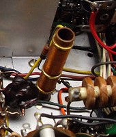
| Adjusting L5 For Maximum Drive On 10 Meters: L5 is the crystal oscillator/buffer plate coil. It is mounted vertically on the chassis near the 6CL6 crystal oscillator/buffer tube. On the top of the chassis, L5 is just behind the 6AX5A rectifier tube. The adjustment is made from the top of the chassis by turning the slug in or out with a screwdriver. To make the adjustment, tune up the transmitter on 28MHz, set the meter to read grid current, and then adjust the coil slug for the highest grid current. The tuning is intentionally very broad, and the usual position of the slug is with the top of the screw about 1/4" to 1/2" from all the way in. |
 Click on the image for a larger view. Click here for a super detailed view. |
| Adjusting R35 For The Proper Modulator Resting Current: Extreme care must be used when adjusting this resistor. It must be adjusted only when the transmitter is turned off, unplugged, and the high voltage filter capacitor C77 has had a chance to discharge. The operator assumes all risk and liability in making this adjustment! R35 controls the screen voltage on the modulator tubes and sets the resting current of the modulator in the absence of modulation. The current must be set to the proper value with the transmitter in phone mode while the transmitter is loaded to a carrier output of 40 Watts. To set the resting current, do the following: 1. Turn down the audio gain control. 2. Tune up the transmitter in phone mode for 40W of carrier output into a dummy load. 3. While the transmitter is delivering 40W carrier, set the meter to read modulator current. The current should be between 75mA and 90mA. (Ideally, it should be 83mA, but anywhere between 75mA and 90mA is OK.) If the current is not within the above range, do the following: 4. Turn off the transmitter and unplug it and make sure C77 is fully discharged! 5. Use an ohmmeter to determine which end of R35 is connected to ground. (This is normally towards the front of the chassis, but after many years or previous repairs this may not be true!) 6. Mark the position of the slider with a permanent marker like a sharpie. 7. Fully loosen the slider. Never move it while it is even slightly tightened, or you can damage the resistor. 8. If the current was too low, move the slider a few turns away from the grounded end of R35. If the current was too high move it a few turns towards the grounded end. 9. Gently tighten the slider to hold it in place. Do Not Overtighten! 10. Perform steps 1 through 3 to read the modulator idle current. 11. Repeat until the idle current is the correct value. |
 Click on the image for a larger view. Click here for a super detailed view. |
| Conditions That Will Require Readjustment Of R35: A variety of conditions will require readjustment of R35. They are as follows: 1. Normal aging of the 1614/6L6GC modulator tubes. As the modulator tubes age, the idle current may slowly change. Readjustment of R35 will be necessary when the idle current gets outside the acceptable range. 2. Aging of the 6AL5 rectifier tube. The 6AL5 supplies bias not only to the keying circuit but also the modulator tubes. Any changes/aging of the 6AL5 may alter the bias on the modulator tubes and require readjustment of R35 to compensate. 3. Replacing the 6AL5 or 5R4 rectifier tubes with solid state diodes. Changing the 6AL5 to solid state diodes will alter (increase) the bias on the modulator tubes and require readjustment of R35. Replacing the 5R4 tube with solid state diodes will increase the high B+ voltage and thus increase the voltage on both the modulator screens and plates. This will again require a readjustment of R35. |
 Click on the image for a larger view. Click here for a super detailed view. |
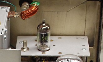
| Adjusting R39 For Proper Keying: Just behind the front panel on the left side of the transmitter is a small subchassis that contains the keying circuit and bias power supply. The potentiometer right next to the 12AU7 keying tube is R39 and it controls the timed sequence keying in the transmitter. You can go to this link to read how the timed sequence keying works in the Johnson Viking Ranger. To adjust the control, set the Operate switch to the Tune position and set the VFO/Crystal switch to the VFO position. Listen for the VFO signal in the station receiver and turn the control one way and the other until you can hear the signal in the receiver even when the key is up. Now turn the control the other way until the signal stops. Key the transmitter, and make sure that the signal stops cleanly when the key goes up. If you don't go far enough, the VFO won't shut off properly on key up. If you go too far the keying will become choppy. You want to find the position where the signal cuts off cleanly when the key is opened, but doesn't make the keying sound choppy. Check on both 80m and 40m, as the keying may cut off on one band but not the other. Find the compromise setting that works best for both 80m and 40m. |
 Click on the image for a larger view. |
 Back to Dr. Greg Latta's
Electrical Engineering and Amateur Radio Pages
 If you have any questions or
comments, you can send E-Mail to Dr. Greg Latta at
glatta@frostburg.edu