QST Article - January 2014:
I originally described this VFO in the January 2014 issue of QST Magazine.
Though this web site greatly expands on the magazine article, I still suggest
that you read the article as it will give you a good, concise view of the
project. If you don't have the back issue of QST magazine, you can go to the
ARRL
QST Site and read the article on-line. (You must be an ARRL member to read
the on-line version.) Not an ARRL member?
You can get a 90 day guest account or
join here.
Introduction:
I love old gear, especially tube gear. As a novice, I started by building an
Ameco AC-1 transmitter. Then I moved up to a Knight Kit T-60. Both of these
were crystal controlled, and it always seemed like someone was already on the
only crystal frequency I had. I got my general ticket after a couple of years,
and I longed for a VFO, but couldn't afford one.
I did eventually get my hands on a used Heathkit HG-10 VFO, but it wouldn't properly drive either of my transmitters. It wasn't until I got hold of a Heathkit DX-40 transmitter that true VFO capability for me became a reality. Wow! What a difference. Of course, that VFO wasn't perfect. It drifted a bit and had some chirp, but that was acceptable and sure beat the heck out of operating with crystals.
A lot of great crystal controlled transmitters are still out there, like the Eico 720, the DX-40, DX-60, and many others, but they sit on the shelf because their owners don't have any crystals, or are unwilling to put up with the difficulties of operating with crystal control. There are also many VFO controlled transmitters out there, like the Johnson Viking Ranger, but their VFOs are old and unstable, or were unstable to begin with. These sit on the shelf too, wasting away. What is needed is a modern VFO that can be used with these transmitters. This VFO was my answer to that call.
The N3ZI Synthesizer:
The heart of the VFO is a synthesizer from N3ZI called the "Super
DDS". You must purchase and build this first. This is a great circuit and
is very reasonably priced. N3ZI has done a beautiful job designing the
synthesizer. It is hard to imagine anything better at such a price. The
synthesizer can output any frequency from 0.1 to 32 MHz in 1 Hz steps. It tunes
very much like an analog VFO and comes with an LCD display if you buy the
"Deluxe" kit. It has 12 memories and an RIT function (very important,
since I use this for keying). For my VFO, I used the standard (or serial) LCD
display. Though not backlit, the characters are large and easy to read.
Note: Since this article was written N3ZI has designed a new version of the
synthesizer, which, among other things, includes a backlit display. This should
work fine, but the pinouts for some of the functions, such as the RIT and VFO
A/B connections, are now different. Be sure to read the manual for the
new synthesizer and make the appropriate changes to the connections for RITa,
RITb, and PB5.
Click Here To Purchase an N3ZI
2018 DDS
When you build the synthesizer, I recommend that you don't use the board
mounted up/down switches.. Instead, use your own push button switches
(normally open, momentary contact) and connect them to the circuit board with
wires so they can be mounted on the front panel. Also I
recommend connecting the rotary encoder to the circuit board with wires.
Wired connections give you more freedom when mounting the circuit board and
related components. Below is a photo of the original completed synthesizer
board. The new synthesizer board is different.

Original N3ZI Synthesizer Board Used in the VFO
Power Supply:
You will need some sort of power supply to power the N3ZI synthesizer board,
the buffer amplifier, and the keying circuit. You could use a 12V wall wart,
but I hate wall warts, since they sometimes lack proper filtering, and prefer
to use an internal power supply. The entire VFO draws only 90mA, so just
about any 12V power supply will do. However, the power supply must be well
filtered. I used a surplus 16V transformer from my junk box, a full wave
bridge rectifier, 1000uf capacitor filter, and a 7812 voltage regulator for my
power supply. The current draw on the supply is so small that it is not
necessary to heat sink the 7812 regulator. Though my transformer is a 16V
transformer, any small transformer with an output of 12V - 17V should also
work. See the schematic diagram and photo below:

Power Supply Schematic Diagram

VFO Power Supply
The transformer is on the left, and the bridge rectifier, capacitor, and
regulator at the lower right.
Buffer Amplifier:
Though the N3ZI synthesizer is a great circuit, the output is quite low, about
225mV peak-to-peak, or 88mV RMS. This is fine if you want to use the
synthesizer as a signal generator, but it is far to low to drive vintage
transmitters, which typically require up to 10 or 20 Volts peak-to-peak. To use
the synthesizer with a vintage transmitter, the output must be amplified.
It turns out that it is very easy to build a two transistor amplifier using a
couple of 2N2222 transistors. The amplifier circuit below yields a peak-to-peak
output of about 5V, which may be enough to drive some vintage transmitters.
N3ZI's original circuit, on his web site, is basically the same as the one
below. I have instituted the changes he suggests to maximize the output of the
buffer amplifier up to 7 MHz. It rolls off above 7 MHz, but still gives useful
output even up to 14 MHz.
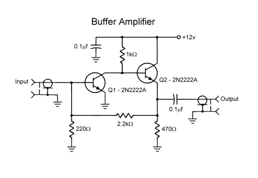
Two Transistor Buffer Amplifier
My buffer amplifier is wired on a small piece of perf /vector board, which also holds the RIT inverter circuit. See the picture below:

Perf/Vector Board With Buffer Amplifier and RIT Inverter.
The buffer amplifier is on the left (red wires) and the RIT Inverter is on the right (black and green wires).
I have a switch on the back panel of the VFO which can be used to bypass the buffer amplifier when the VFO is used as a signal generator and the extra output isn't needed. The red switch can be seen at left in the photo above. A block diagram of the bypass switch wiring is shown below:
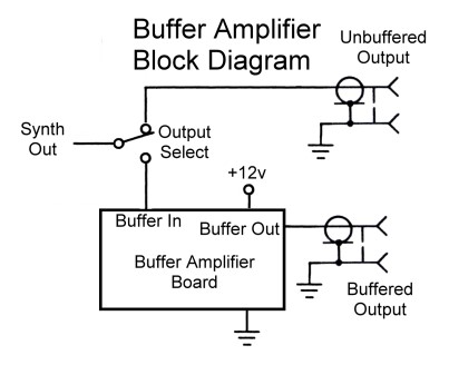
Buffer Amplifier Bypass Switch Wiring
1 to 2 Step Up Voltage
Transformer:
The output with the two transistor amplifier is about 5 volts peak-to-peak, and
this is sufficient to drive many vintage transmitters. However, some
transmitters, such as my Eico 720, need more drive. To drive such transmitters,
you will need to use a 1 to 2 voltage (1 to 4 impedance) step up transformer.
The output of the two transistor amplifier is low impedance, and it is possible
to get more output by using a transmission line transformer to step up the
voltage. It is very easy to make a 1 to 2 voltage (1 to 4 impedance) step-up
transformer and it is pretty much foolproof. All you need is some small wire
and the proper toroidal core.
My transformer is wound on an FT-50A-61 ferrite toroid core (AL=75
mH/1000 turns). Cores are available on line from several sources such as
hamfests or on-line at Amidon Associates or Palomar Engineers:
www.amidoncorp.com
palomar-engineers.com
Do not use a powdered iron core. These won't provide enough inductance. The
core is not critical in size or material as long as it is a ferrite core with
an AL value of at least 75 mH/1000 turns. If you have an unknown core, it is
easy enough to try it out. If it works, fine. If not, you will need to try
another core.
I used #24 enameled magnet wire to wind my transformer, but just about any
insulated wire that is small enough so that 11 bifilar turns can be wound on
the toroid will work. Double the wire up, and then carefully wind 11 turns on
the toroid, keeping the wire neat and parallel to itself. The first pass
through the toroid counts as turn number one. If you wind an extra turn or two
the transformer will still work fine. Strip the ends of the four leads. To
strip enameled wire, burn about 1/2" with a lighter and sand off the ash.
Use an ohmmeter to identify the two windings and then wire up the transformer
as shown in the schematic and photo below:
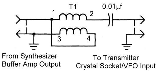
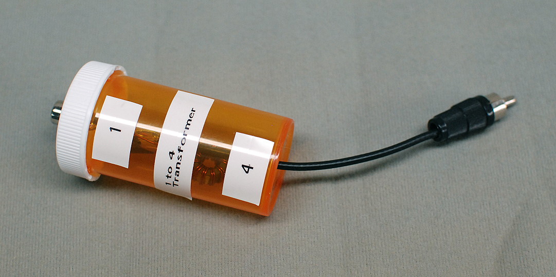
1 to 2 Voltage Step Up Transformer
I built my transformer into a pill bottle I got from my local pharmacy. For the input to the transformer, I mounted a female RCA jack on the top of the pill bottle. This is visible at left in the photos below. I used a short length of RG-174 coax with a male RCA plug on the end ("pigtail") for the output from the transformer. This is visible at top center in the photo below. This piece of coax must be kept as short as possible. The value of the blocking capacitor is not critical. Anything from 0.001uf up to 0.01uf will work fine.

Notated Picture of the 1 to 2 Voltage Step Up Transformer
Click for a close up view.
Below is a picture of the completed transformer mounted
inside the pill bottle:
Completed Transformer Mounted Inside A Pill Bottle
Click for a close up view.
Do not try to extend the cable (pigtail) to the transmitter. This is high impedance and must be kept very short. In fact, it is perfectly acceptable to mount the transformer inside the transmitter for best performance. I decided to do this with my Viking Ranger transmitter by mounting the transformer inside the external VFO input I added to the Ranger.
RIT Keying Circuit:
The VFO must be disabled or somehow moved off frequency during receive periods.
Otherwise, it will interfere with reception. The N3ZI synthesizer board
contains an RIT (Receiver Incremental Tuning) input (pin
J3-8) that, when connected to ground, shifts the VFO frequency by an amount
equal to the RIT offset. If the RIT offset is large enough (for example, 1MHz,
which is what I use), the new frequency will be well outside the receiver
passband, and the VFO won't interfere with reception.
We could connect a switch to the RIT input. When it is open, the VFO would be
on frequency, and when closed, off frequency. We could then open the switch
every time we wanted to transmit, but that is very inconvenient. We could also
use an extra pair of contacts on the transmit/receive relay to handle the
switching, but in both cases the VFO is continuously on while transmitting.
That is fine when running AM phone, but when running CW it makes it very
difficult to monitor our sending. The best solution is to use the key itself to
bring the VFO on and off frequency. That is, we want the key itself to key
the VFO.
First, we need an inverter circuit that will protect the RIT input in case we
connect it to something we shouldn't, and also invert the RIT input so that
closing a switch (like the key) will bring the VFO on frequency,
but keep the VFO off frequency when the switch is open. This is easy to
do using one 4.7kohm resistor and a 2N2222 transistor as shown below:

RIT Inverter Circuit
Click for a close up view.
Note: Since this article was written N3ZI has designed a new version of the
synthesizer.
This should work fine, but the pinouts for some of the functions, such as the
RIT and VFO A/B connections, are now different.
Be sure to read the manual for the new synthesizer and make the
appropriate changes to the connections for RITa, RITb, and PB5.
The RIT input is on pin J3-8 of the synthesizer board (but see the note
above for new synthesizer boards). For normal operation, the RIT keying (SPOT)
switch is closed. Q5, which is normally turned on, then pulls the RIT
input low and puts the VFO off frequency. When the input to Q5 is
brought to ground, Q5 turns off, the RIT input goes high, and the VFO goes
on frequency.
Opening the RIT Keying (SPOT) switch lets the RIT input go high and
brings the VFO on frequency regardless of what is present at the input
of Q5. This allows the operator to "SPOT" or listen to the VFO in the
station receiver, regardless of what is present at the RIT keying input.
I mounted my RIT inverter circuit on the same little piece of perf board that I used for the two transistor buffer amplifier. See the picture below:
Perf/Vector Board With Buffer Amplifier and RIT Inverter.
The buffer amplifier is on the left (red wires)
and the RIT Inverter is on the right (black and green) wires..
Complete Block Diagram of the VFO:
A complete block diagram of the VFO (less the power supply) showing how the synthesizer board, RIT keying circuit, and buffer amplifier are interconnected is shown below:

Complete Block Diagram of VFO
Click on any section of the diagram for more information on that part of the
VFO.
Note: Since this article was written N3ZI has designed a new version of the
synthesizer.
This should work fine, but the pinouts for some of the functions, such as the
RIT and VFO A/B connections, are now different.
Be sure to read the manual for the new synthesizer and make the
appropriate changes to the connections for RITa, RITb, and PB5.
You can also click here for an inside view the complete VFO showing the buffer amplifier/RIT circuit perf board, synthesizer board, and power supply.
Keying Amplifier:
Now that we have a way to key the VFO, we need a circuit that will allow the
key to control both the VFO and transmitter at the same time. The problem is
that some vintage transmitters have a negative voltage at the key, and others
have a positive voltage at the key. These voltages are sometimes quite high
(several hundred volts), and sometimes large currents (perhaps 250mA) need to
be keyed. Our circuit must be able to handle all of these situations.
The circuit below does the job nicely. Though some folks don't like to use a
battery, it greatly simplifies the circuit. You just have to remember the
battery is there and replace it once in a while!
If your vintage transmitter has a negative voltage at the key (i.e. it is grid
block keyed) you don't need Q3. If your vintage transmitter has a
positive voltage at they key (i.e. it is cathode keyed) then you must
use Q3. Q3 is an NPN transistor that must be able to handle the positive
voltage and current that must be keyed by your transmitter. This varies greatly
from transmitter to transmitter. If Q3 can handle about 400V and 250mA, than it
will probably work OK in most situations. I used an NPN power transistor in a
TO-3 case that was originally intended as the horizontal output transistor in a
TV set. These can typically handle higher voltages and currents. For more
information on what to use for Q3, see Finding A Transistor For
Q3 below.
Note that the keying input to the amplifier is negative with respect to
ground. This is no problem with a mechanical key or bug, but if you use a
keyer be sure to use the negative keyer output that was designed for
vintage, grid-block keyed transmitters.

Keying Amplifier Schematic
Click for a close up view.
The key is connected to the input of the amplifier, and a cable is run from
the Q4 output to the RIT keying input on the VFO. Grid
block keyed transmitters should be connected to the "Center Negative"
key jack. Cathode keyed transmitters should be connected to the "Center
Positive" jack.
The operation of the keying amplifier is straightforward. Under key up
conditions, the 1N4005 diode prevents any negative voltage at the "Center
Negative" key jack from flowing back through the battery and transistors
Q3 and Q4. Under key up conditions, Q3 and Q4 are turned off. When the key is
closed, any transmitter connected to the "Center Negative" jack is
keyed. Q3 and Q4 are turned on because the negative lead of the battery is
connected to ground through the diode and the closed key. Q3 then keys any
transmitter connected to the "Center Positive" jack, and Q4 keys the
VFO, bringing it on frequency.
I chose to mount my keying amplifier in a small minibox separate from the VFO. That would make things easier whenever I wanted to use the VFO as a signal generator in my shop. Originally intended for use only with my cathode (positive) keyed Eico 720 transmitter, I used a short pigtail rather than a 1/4" jack and cord to connect to the key jack on the transmitter. I later added keying for grid-block (negative) keyed transmitters.

Keying amplifier mounted in a small minibox.
In the photo above, the key plugs into the 1/4" jack on the right side of the box. For positive keyed transmitters, I decided to use a pigtail with a 1/4" plug on it rather than a jack. Negative keyed transmitters plug into the 1/4" jack on the front of the box, and the RIT keying output is the RCA jack on the front of the box. When I get around to it, I plan to add a switch on the battery to turn it off when not in use. (In the past I have accidentally closed the contacts on my bug overnight and ruined the battery.) The switch would prevent such occurrences.
Finding A Transistor For Q3:
I am often asked "What transistor should be used for Q3?" The answer
is any NPN transistor that can handle the voltage and current at the key
terminal of your transmitter. These are typically less than 400V and perhaps
250mA. One way to find an appropriate transistor for Q3 is to go to an
electronic parts web site, such as Mouser Electronics:
https://www.mouser.com/
In the search box type the following:
transistor bipolar npn 400v through hole
This will bring up a list of transistors that should work. An example is the
following:
610-BU406
This transistor can handle up to 400V and 15A, which is more than enough for
about any situation. For most situations, a heat sink will not be needed on the
transistor.
You may need to change the 1.5 kohm resistor in the base lead of Q3. If
this is too high, Q3 will not fully key your transmitter. If too small, the
load on the battery will increase. Experiment until you find the highest value
at which your transmitter will key properly. Q3 does add some grid bias to the
keyed circuit, so it will behave a little differently than when you use a
mechanical key.
Connecting the VFO Output to the
Transmitter:
Connecting the VFO to the transmitter varies from one transmitter to the next.
If your transmitter has a separate VFO input, then try that first. Some
transmitters may also require you to throw a switch or use a jumper as well.
For example, my Eico 720 has a VFO input on the back, but it also has a slide
switch that must be set to VFO to work properly.
Lacking a VFO input, you must use the crystal socket. Check the transmitter
schematic. In many/most transmitters, such as my
6CL6 transmitter or
Johnson
Viking Ranger, one side of the crystal socket is connected to ground. In
such a case, connect the hot lead from the VFO to the ungrounded side of the
crystal socket, and connect the ground lead from the VFO to the grounded side
of the crystal socket.
In some transmitters, neither side of the crystal socket is grounded. In these
cases, one side of the crystal is connected to the grid of the oscillator tube,
either directly or through a coupling capacitor. Connect the hot lead from the
VFO this side of the crystal socket and the ground lead of the VFO, though a
0.001uf capacitor, to the other side of the crystal socket. The coupling
capacitor prevents any DC that might be on the crystal socket from being
shorted to ground. If that doesn't work, try connecting the ground lead of the
VFO directly to ground, rather than the other side of the crystal socket. You
will have to experiment to see what works in these situations.
The actual physical connection to the crystal socket can be a problem. In the
crudest/simplest case, it can be made by simply stuffing the wires into the
socket pins. But this is not a very poor solution, and should not be used in
the long term. If the crystal socket is part of an octal tube socket, then you
can purchase an octal plug to make the connection or use the base from a
defective octal tube. Octal socket plugs are available from Antique Electronic
supply. Click on the link below:
Octal Tube Base:
Antique Electronic Supply Part Number:
P-SP8-476
If you have a defective octal tube, put it in a bag and break the envelope with
a hammer or vise, clean out the base, and then unsolder the wires from the base
pins. Be sure to wear safety goggles when working with glass.
Another option is to find a defective FT-243 crystal or one that is not in the
ham bands. This can be disassemble and the crystal can be removed. A hole can
then be drilled in the top for a cable to pass through and the cable can be
connected to the pins.
Many years ago, connectors were made for plugging television sets into a wall
socket using twin lead. These will also work, but are hard to find now.
Important: regardless of how you make the connection, if you are using the
1:2 transformer you must keep the leads from the transformer to transmitter as
short as possible.
I made adaptors for my various transmitters that all go to a female RCA
connector through very short wires. I can then have a male RCA plug on my
1:2 transformer and the cable from my VFO. I can
then easily use the VFO with or without the 1:2
transformer and with any of my vintage transmitters or my
6AG7 VFO amplifier.
Connecting The Complete System to a Vintage Transmitter
The diagram below shows how to connect the VFO and keying amplifier to a typical transmitter:
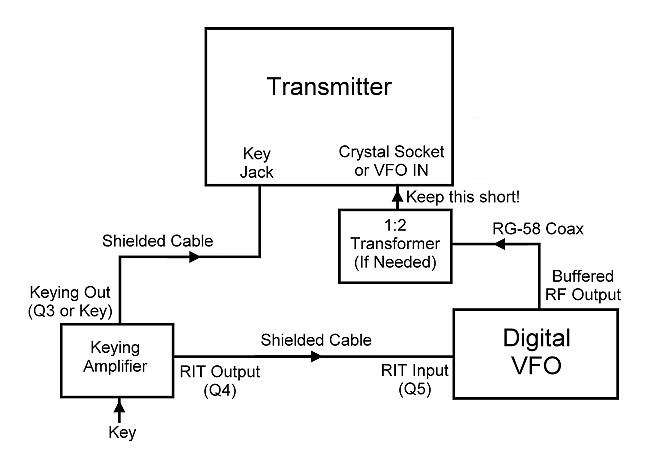
Overall system diagram showing how to connect the VFO and keying amplifier to a
vintage transmitter.
Click on any section of the diagram for more information on that part of the
VFO.
To connect the VFO and keying amplifier to a vintage transmitter, you must
make the following connections:
1. The key, bug, or keyer (center negative) is connected via shielded cable to
the keying input of the keying amplifier.
2. The appropriate keying output from the keying amplifier (center positive for
cathode keyed transmitters such as the Eico 720, center negative for grid-block
keyed transmitters, such as the Johnson Viking Ranger) is connected via a
shielded cable to the key jack of the transmitter.
3. A shielded cable runs from the RIT output of the keying amplifier (Q4) to
the RIT input of the VFO (Q5).
4. A cable made of RG-58U coax cable is connected between the buffered output
of the VFO and the crystal socket or VFO input of the transmitter. Do not
use audio cable for this connection. If the 1:2
transformer is used, it can be connected to the transmitter with wires,
twin lead, or coax cable, but it should be kept as close as possible to the
transmitter input.
Using the VFO with a Vintage
Transmitter:
Once you have the system connected as shown above, it is time to get the
transmitter on the air.
The first thing to do is to set the RIT offset on the synthesizer to about
1MHz.. This is done as follows:
1. Be sure that the "Display RIT" switch is off.
2. Press, and while holding, the tuning knob activate the up/down push
buttons until the display shows "dF" (for difference in
Frequency).
3. Release the tuning knob and rotate the tuning knob for the desired offset.
This is not critical, but I typically use a setting of 1MHz.
4. After you have set the desired offset, simply wait and the display will
return to normal.
Next, you want to set the desired tuning step. For CW, I find that 10Hz is fine
on 80m and 40m. You may wish to decrease it further (to 5Hz or 2Hz) if you
regularly operate on any of the higher frequency bands. To set the tuning step
size, do the following:
1. Press, and while holding, the tuning knob activate the up/down push
buttons until the display shows "SP" (for SteP)
2. Release the tuning knob and rotate the tuning knob for the desired offset.
This is a matter of personal preference, and you can experiment here, but I
typically use a setting of 10Hz on 80m and 40m, and 5Hz or 2Hz on the higher
frequency bands..
3. After you have set the desired step size, simply wait and the display will
return to normal.
As a preliminary test, choose one of the VFO memories and set it to a frequency
of your choice, say 7MHz. Tune your receiver to the same frequency, and
open the "SPOT" switch. You should be able to hear the signal
in your receiver. Close the "SPOT" switch and, if the system
is connected properly to the keying amplifier, the signal should go away. Press
the key and you should again here the signal in the receiver. If the RIT keying
is working properly, you will be able to copy your keying in the receiver. If
you turn on the "Display RIT" switch, the display should show the VFO
frequency while the key is down, and the VFO frequency plus the RIT offset when
the key is up.
Read the transmitter manual to see what VFO/crystal frequencies you are
supposed to use with your transmitter. With many transmitters, the VFO/crystal
frequency will be in the 80m band (3.5MHz) for 80m, and it will be in the 40m
band (7MHz) for all other bands. However, some transmitters, such as the Viking
Ranger, use a VFO/crystal frequency of 160m (1.8MHz) for 160m and 80m, and a
40m frequency (7MHz) for all of the other bands. You must remember that your
output frequency will be the VFO frequency or an integer multiple of it.
For instance, if you are on the 15m band and wish to operate on 21.027MHz, you
will have to set the VFO to 1/3 of your desired operating frequency, or
7.009MHz. (This is what you had to do when using crystals or a vintage VFO, and
you must still do it here. Such are the joys of operating vintage equipment.)
You can try the system with and without the 1:2 step up
transformer. Most transmitters will need the transformer. If the VFO is
driving your transmitter properly, your transmitter should behave about the
same as when it is used with crystals. However, if you must turn up the drive
control much more than normal, or if your grid current is too low, or if the
transmitter is unstable, you either don't have enough drive, or you haven't
connected the VFO output properly to your transmitter.
I have used this VFO system successfully with my Eico 720 transmitter, my
Johnson Viking Ranger, my
6CL6 transmitter, and my
6AG7 amplifier. With all of these I use
the 1:2 step up transformer. This VFO is as stable
or more stable than modern transceivers. If you follow the calibration
procedure in the N3ZI synthesizer manual, you can get the accuracy of the VFO
to within 1Hz at 10MHz, which is better than most modern transceivers!
Spotting the VFO in the Receiver:
In a modern transceiver, the transmitter is automatically set to the receiver
frequency as you tune the receiver. But in a vintage station you must learn to
separately set the the transmitter frequency to the receiver frequency. This is
called "Spotting" the transmitter, and it is a very important
technique to learn. (Note that spotting the transmitter is NOT the same as
zero beating the transmitter!) Properly spotting your transmitter takes a
little practice, and if not done properly your transmitter frequency can be as
much as 2kHz away from your receive frequency! This will cause you to lose QSOs
and/or to cause QRM on the bands.
Spotting the VFO/transmitter involves turning on the VFO with the spot switch
(opening the spot switch) and then adjusting the VFO until the signal is heard
in the receiver. (You may also need to engage a "spot" setting on the
transmitter). The problem is that many older receivers lack single signal
selectivity, and it is possible to hear the VFO at two places on the
dial, rather than one. You must learn by practice which of those two places is
the correct one.
As the VFO is tuned, the audio pitch in the receiver will change, and there
will be a particular pitch where the receiver response is the best. For better
receivers with "single signal" selectivity, there will be only
one setting of the VFO where the response is best. This is obviously the
correct setting. Count yourself lucky if you have one of these receivers.
For receivers which lack single signal selectivity there are two
settings of the VFO which will be picked up by the receiver. If one is
noticeably louder than the other, that is the correct VFO setting. You may have
to listen carefully (or look at the S-meter, if the receiver is so equipped) to
hear the difference, but once you are aware of it you should be able to set the
VFO to the correct frequency without too much difficulty.
For receivers with very poor selectivity (such as regenerative receivers),
there will be two places where you can pick up the VFO signal, and there
will be no noticeable difference in the receiver response. In such
receivers, as you tune through a station from the low frequency side, the pitch
will start high and then go down so low as to be inaudible ("zero
beat") and then go back up. We say that you can tune in the signal on
either the low frequency side of zero beat or the high frequency side of zero
beat. The first step in successfully using such a receiver is to always tune
the station in on the low frequency side of zero beat. This means that if
you tune the receiver to a slightly higher frequency, the audio pitch
will go down and vice-versa.
Assuming you have tuned your receiver on the low frequency side of zero beat,
adjust the VFO so you can hear the signal in your receiver. If have the correct
VFO setting, the audio pitch will go down if you slightly lower
the VFO frequency. If the pitch goes up, you have the VFO set to the wrong
frequency. In such a case, tune the VFO so the audio pitch goes down and then
back up on the other side of zero beat. When you have the correct VFO setting,
the audio pitch will go down if you slightly lower the VFO
frequency. (Likewise, if you slightly raise the receiver
frequency the pitch should go down. This might sound complicated, but
after you do it a few times you will get used to it and then do it without much
thought.
Failure to properly spot the VFO/transmitter in the receiver is why many modern
hams fail to make successful QSOs with vintage gear or regenerative receivers.
Failure to properly spot your transmitter frequency can place your transmitter
frequency as many as 2kHz or more off from your receiver frequency! This causes
QRM and the loss of QSOs.
Vintage Operating Procedures: Answering A
CQ:
Operating vintage equipment is a little different than when using modern
equipment because it involves spotting the VFO in the
receiver. When answering a CQ, tune in the station on the receiver. If you
have a receiver with poor selectivity, be sure to tune the signal in on the
low frequency side of zero beat. Enable Spot on the VFO and
Spot the VFO in the receiver. Be careful to do this
properly. Fine tune the pitch of the VFO so the pitch of the VFO is the same
as the pitch of the other station If you can't get the pitch close enough,
you will need to decrease the VFO step size. (See Using
the VFO with a Vintage Transmitter above). No NOT zero beat the VFO! When
the VFO is spotted correctly and the audio pitch of the VFO signal is the same
as the station you are answering, you are on the proper frequency and can can
call the other station.
Remember, your operating frequency will be the VFO frequency or an integer
multiple thereof, so the VFO may not show your actual operating frequency.
Vintage Operating Procedures: Calling
CQ:
When calling CW, you must first tune the receiver to a clear frequency. Listen
for a while to make sure the frequency is clear. Spot the
VFO in the receiver, being careful to do this properly. Call QRL? and
listen carefully for any response. A response of QRL, YES, or C means
that the frequency is in use, and you need to find another frequency. Just for
good measure, call QRL? again to be sure the frequency is clear. If the
frequency is in use, find another one, Spot the VFO again, and repeat. Only
call CQ when you are sure the frequency is clear.
Remember, your operating frequency will be the VFO frequency or an integer
multiple thereof, so the VFO may not show your actual operating frequency.
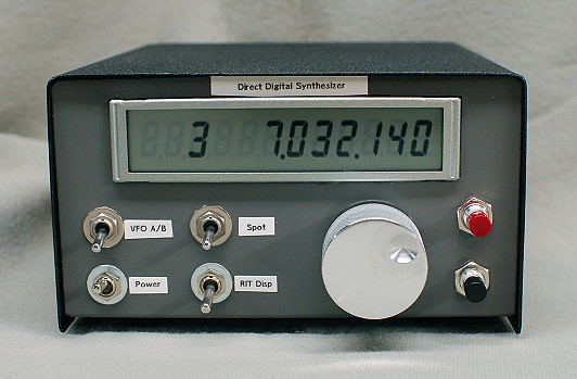
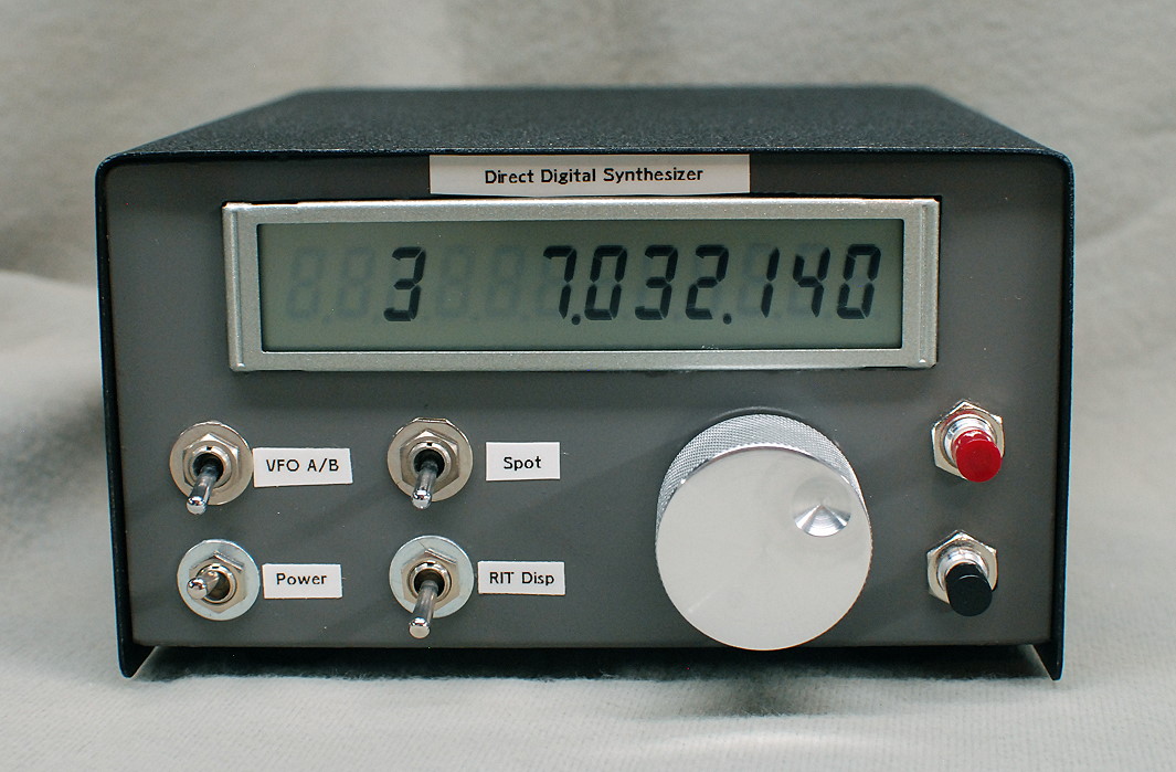
| Front View: This is a front view of the digital VFO. The frequency can be set within 1 Hz, but I usually keep the frequency step size to 10Hz, which is more than adequate for CW. The frequency step size can be easily changed to suit your needs. The large tuning knob is of my own design. Turning the knob sets the frequency, and pushing the knob activates the synthesizer menus. The black and red push buttons, along with the VFO A/B switch, select one of 12 different memories. The buttons are also used to program the synthesizer. I use one memory for each band, 80m, 40m, 30m, and 20m, and have six additional memories programmed with the six center channel frequencies of the 60m band. One of the memory locations is labeled VFO A/B and can actually hold two frequencies. The VFO A/B switch selects which frequency is programmed or used. The Spot switch turns on (keys) the synthesizer so that the operator can spot the transmitter frequency in the station receiver. The RIT Display switch causes the RIT frequency to be displayed. As explained elsewhere, I use the RIT to keep the VFO off frequency during receive periods, unless the Spot switch is turned on. Keying the VFO brings it on frequency while the key is down, and takes it off frequency when the key is up. (Unless the Spot switch is thrown.) I typically don't use the RIT Display switch for anything, but it is there in case it is needed. |
Click on the image for a larger view. Click here for a super detailed view. |
| Rear View: One the back of the VFO there are two outputs, one that is buffered/amplified and one that is not. The buffered output is used when driving a transmitter, and the unbuffered output is used when the VFO is used as a signal generator. The switch selects which one you wish to use. The RIT keying jack is normally connected to the RIT output on the keying amplifier. When grounded, it brings the VFO on frequency. When open, the VFO is off frequency by an amount equal to the RIT offset unless the SPOT function is activated. |
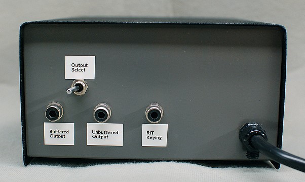 Click on the image for a larger view. Click here for a super detailed view. |
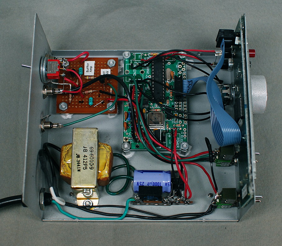
| Inside View: This is an interior view of the VFO. The synthesizer board is mounted at top center. The power supply is at the bottom, and the perf board containing the buffer amplifier and RIT inverter/keying circuit is at top left. The red switch on the back panel at left selects either the buffered or unbuffered output. The rotary encoder, LCD display, and other switches are mounted on the front panel on the right. |

Click on the image for a larger view. Click here for a super detailed view. |
 Back to Dr.
Greg Latta's Electrical Engineering and Amateur Radio Pages
Back to Dr.
Greg Latta's Electrical Engineering and Amateur Radio Pages
 If you have any questions or
comments, you can send E-Mail to Dr. Greg Latta at
glatta@frostburg.edu
If you have any questions or
comments, you can send E-Mail to Dr. Greg Latta at
glatta@frostburg.edu