Important Safety Note: Working on or testing equipment such as the Viking Ranger is extremely dangerous since very high voltages are present when the equipment is turned on, and may even be present when the equipment is turned off and unplugged. If at all possible, do all work with the equipment off and unplugged and be sure that the capacitors are properly discharged before working on the equipment. The operator assumes all risk and liability in such matters! Do not work on this type of equipment unless you are experienced with working around very high voltages!
Introduction:
The internet is full of modifications to "improve" the Johnson Viking
Ranger. Many of these are pure bunk. It amazes me when someone claims to
"restore" a Ranger by tearing out the original modulator circuit and
putting in a completely different circuit. This isn't rebuilding the Ranger, it
is perverting the Ranger!
The original engineers did a great job in designing the Ranger. As a result,
very few modifications are needed or recommended. Remember, the Ranger is now
an antique. Modifying the Ranger to "improve" it can seriously ruin
the resale value of the transmitter. You are only the temporary steward of your
Ranger. It will someday pass on to someone else. Please leave something to pass
on. Whatever changes are made, they should be reversible to the extent
possible.
Line Cord And Fuse Holder
Replacement:
Though I recommend against many modifications, this is one that should
be done. Operator safety demands that the original line cord and fuse holder be
replaced by a modern 3-wire grounded cord and a chassis mounted fuse holder.
Aside from operator safety, the line filter on the Ranger is such that if the
chassis is not grounded through the antenna connection or a separate ground
connection, as much as 60V AC can be present on the chassis relative to
ground. This can give you a slight shock when connecting the antenna, but
worse yet it can blow out a solid state component, such as an external VFO,
when it is connected to the Ranger!
The Ranger draws less than 5A when in operation, so an 18/3 or larger line cord
is fine. The only disadvantage to larger line cords is that they can be very
stiff and may require enlargement of the original line cord hole on the Ranger.
If you must enlarge the line cord hole, be extremely careful when drilling
it out! It very easy to lose control of the drill and damage components.
You will also need a strain relief that can fit into the line cord hole on the
Ranger. Many times you can get the line cord and strain relief from a discarded
piece of equipment.
Mouser Electronics carries line cords,
fuse holders, and strain reliefs. The line cord and fuse holder that I used are
as follows:
3 Conductor Line Cord:
Mouser Part Number:
562-311007-01
Single fuse holder:
Mouser Part Number:
534-3536
I selected a strain relief from a big assortment that I had in stock. You will
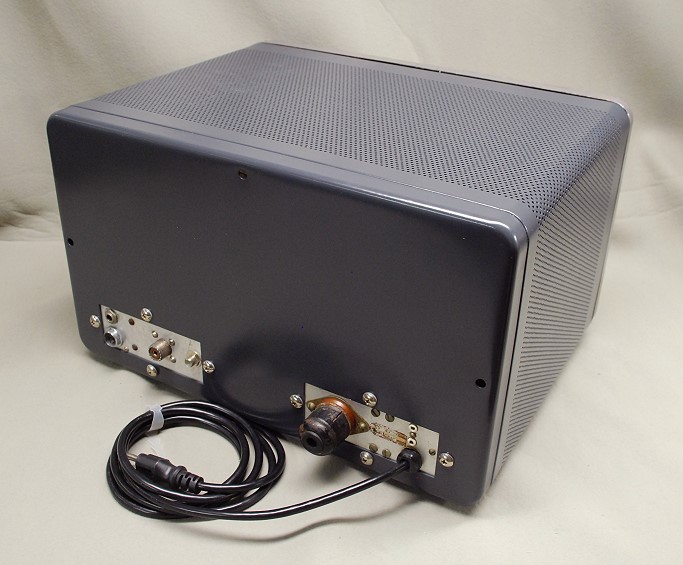
have to find one on your own. A photo of the Ranger with the new line cord
installed is shown below:
Ranger With New Grounded Line Cord Installed
Click on the image for a larger view.
Click here for a super detailed
view.
Finding a location for a fuse holder was difficult because anything mounted
on the rear panel must be located in the two rectangular regions that are not
covered by the cabinet. No location on the outside of back panel for a hole
mounted fuse holder could be found, but it turns out that there is just enough
room on the inside of the back panel near the auxiliary connector to
squeeze in a molded base fuse holder (with a 5A fuse). Mounting the fuse inside
meant that replacing the fuse would require removal of the Ranger from its
cabinet, but there was really no other way to mount a fuse.
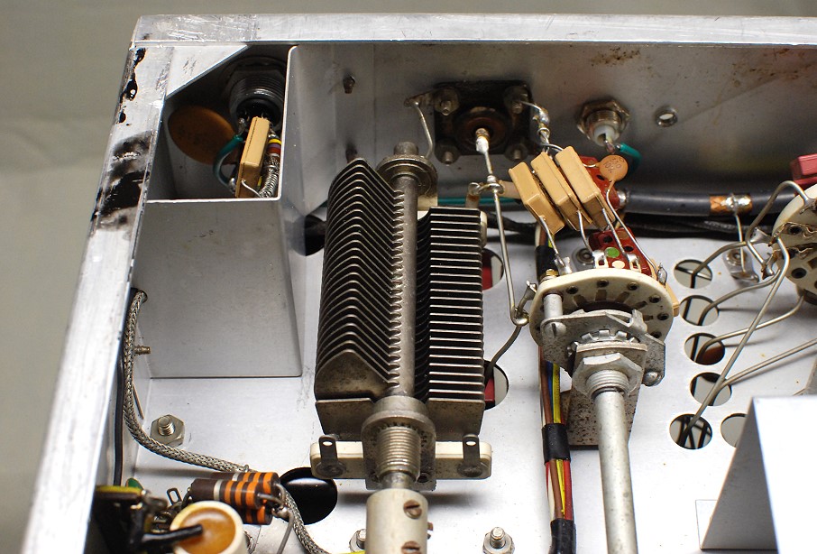
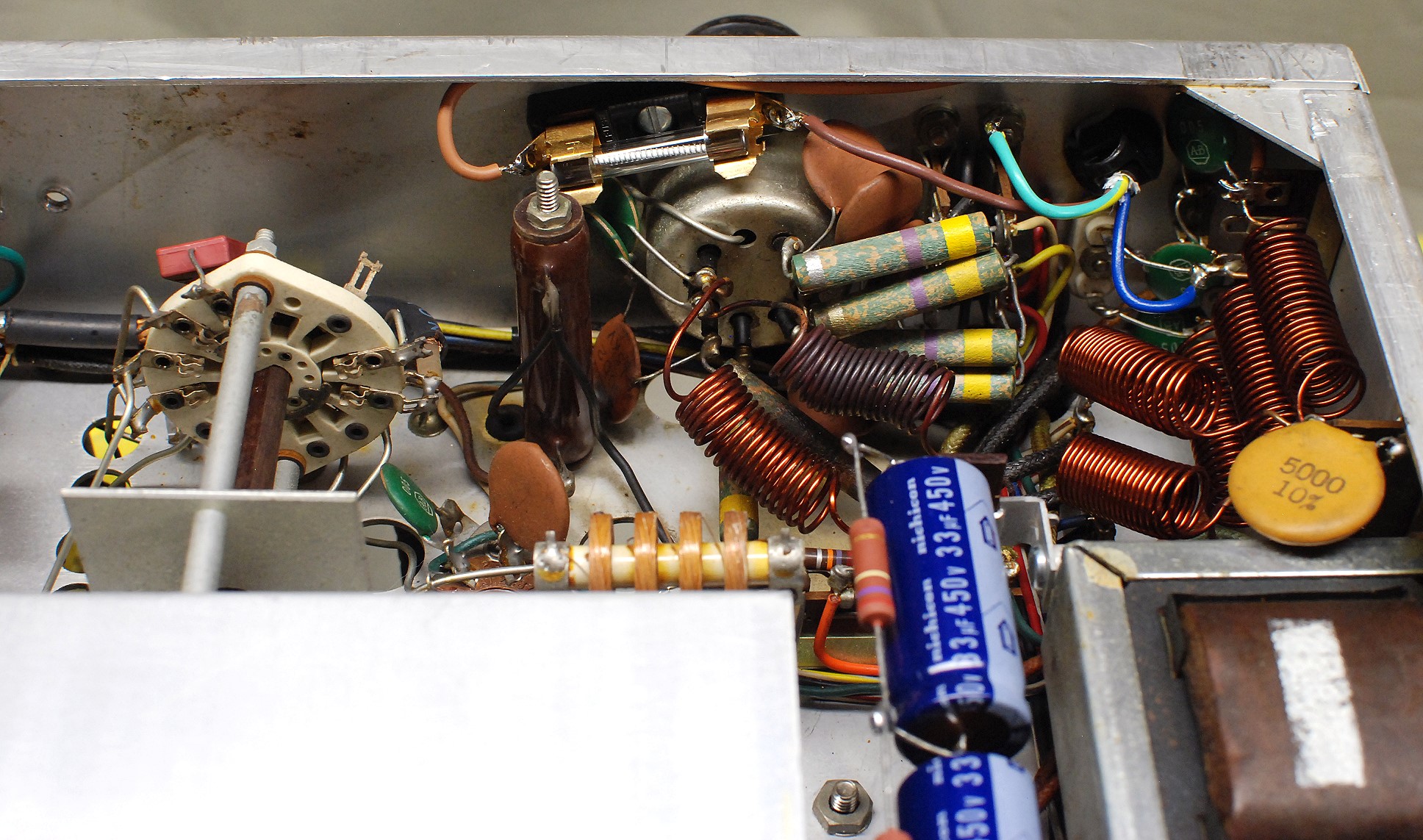
Very carefully drill a hole for the fuse holder and mount the fuse as shown at
top center in the photos below. Code requires that the fuse is wired in series
with the hot AC wire, which is the one connected to the narrower
blade on the AC line plug. For the cord I purchased, the hot AC lead (narrow
plug blade) was brown, the neutral lead (wide plug blade) was blue, and the
ground lead was green/yellow. (Your cord may be different). I mounted a solder
lug under one foot of the terminal strip holding the four
"firecracker" RF chokes, and I soldered the ground lead to that. You
can see the connections clearly in the photos below:
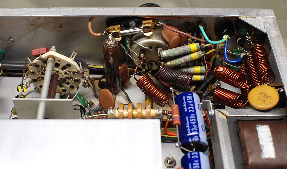
A molded base fuse holder with a 5A fuse can be squeezed in
on the back panel as seen at top center in this photo.
Click on the image for a larger view.
Click here for a super detailed
view.
Push-To-Talk Jack:
Though the Ranger is a great CW rig, the mode where it really shines is on AM.
When operating phone, I prefer to operate in push-to-talk (PTT) mode. My D-104
mic was equipped with a PTT switch, and J1, the Ranger mic jack, has a
connection for the PTT line from the mic, but it not connected to anything.
There are instructions in the Ranger manual for wiring the transmitter
internally for PTT, but these extensively modify the Ranger itself, and I
recommend against such a modification.
A far better option is the bring the PTT line outside the transmitter and
connect it to an external PTT circuit. That way you can change the PTT
circuit easily without going into the transmitter, and without making extensive
modifications to the transmitter itself. Carefully drill a hole for the RCA
jack just to the right of the antenna connector on the back panel. (Don't drill
it too far away, or it won't fit through the rectangular cutout in the
cabinet). Run a wire from the center of this jack to pin-2 of the mic
connector. Keep the wire against the chassis, away from antenna connector and
coupling capacitors, and as short as possible. There is a gap under the metal
shield around the mic jack that you will be able to fit it through. (You may
have to remove the shield to solder the wire to the mic connector). See the
photos below:
|
|
|
After the modification, you can connect your external PTT circuit to the PTT
jack. The jack in normally open, but shorted to ground when the PTT switch on
the mic is pressed.
The easiest way to use the PTT jack is to use it to switch a 12V DC relay off
and on. The relay can then key the transmitter, mute the receiver, activate an
antenna changeover relay, light an "On The Air" sign, etc. The
possibilities are endless.
Replacement Of Vacuum Tube Rectifiers With
Silicon Rectifiers:
One of the first things I noticed after restoring my Ranger and putting it on
the air was how hot it ran, even in CW mode, when the modulator tubes were
disabled. A lot of the heat seemed to becoming from the area of the
5R4 and
6AX5A
rectifier tubes. At the time the Ranger was designed, solid state diodes had
not yet been perfected, and none were used in the Ranger. I thought it might be
a good idea to try replacing the vacuum tube rectifiers with modern solid state
silicon diodes. This isn't to reduce the heating of the power transformer, as
some people might think, but rather to eliminate the heat produced by the
rectifier tubes. The heat from the filaments in the rectifier tubes alone
amounts to 10W for the 5R4 and 7.6W for the 6AX5A. That is almost 18W just for
the filaments alone, let alone the heat produced by the voltage drop across the
tubes. With solid state diodes the heating in the rectifiers would drop to less
the approximately 3W.
Replacing the rectifier tubes with solid state diodes would eliminate the
heating in the rectifier tubes, but increase heating elsewhere
throughout the transmitter due to increased high and low B+ voltages. The only
way ultimately tell whether tube or diode rectifiers would work better would be
to actually make the change. Fortunately, it is possible to make the change in
a completely reversible form, with no permanent modifications to the
Ranger. The secret is to mount the diodes in octal tube bases, which can
be obtained from Antique Electronic
Supply. I found that when the vacuum tube rectifiers were replaced with
solid state diodes, the overall heating in the transmitter was noticeably
reduced, so I recommend this modification.
To make the modification you will need two octal tube bases and eight 1N4007
diodes. These can both be obtained from Antique Electronic Supply and other
suppliers as well. The part numbers from Antique Electronic Supply are:
Octal Tube Base:
Antique Electronic Supply Part Number:
P-SP8-476
1N4007 1000V Diode:
Antique Electronic Supply Part Number:
P-Q1N4007
For the 6AX5A replacement, use two single diodes and an octal tube
socket. Wire one diode from pin 3 to pin 8, with the cathode connected
to pin 8. Wire the other diode from pin 5 to pin 8, also with the
cathode connected to pin 8. Don't solder pin 8 until both diode leads
have been connected to it, and make sure that both are soldered. (The pins are
numbered from 1 to 8 clockwise from the key when viewing the socket from the
bottom). Label this octal base clearly "6AX5". The octal bases are
not interchangeable! Place this into the 6AX5A socket.
For the 5R4 you will need one octal tube base and six diodes. First make two
three-diode strings, connected in series from anode to cathode. Keep the
connections between the diodes relatively short. I made my strings so the
middle diode was horizontal and the outside diodes were vertical. Wire one
string from pin 4 to pin 8, again with the cathode end connected to pin
8. Wire the other string from pin 6 to pin 8, also with the cathode end
connected to pin 8. Don't solder pin 8 until both diode leads have been
connected to it, and make sure that both are soldered. Label this octal base
clearly "5R4". The octal bases are not interchangeable! Place
this into the 5R4 socket.
Keep the original rectifier tubes in a safe place in case you ever want to go
back to them instead of the diodes. You will notice that your Ranger is
noticeably cooler after you have replaced the tubes with the solid state
rectifiers.
With the diodes in place, the low and high B+ voltages will be higher. This
will require that you readjust
R35 for proper modulator resting current. You will also be able to get more
RF output from the Ranger than before, but I do NOT recommend tuning the
Ranger for more output. That isn't the point of replacing the rectifier
tubes with diodes. Tuning for more output defeats the point of using the
diodes, which is to lower the transmitter temperature. Increasing the output
overloads the 6146 final, the modulator section, and the power supplies which
are NOT designed for the extra output.
I recommend that you tune and load the Ranger for the following outputs:
In CW Mode - 45W output
In AM Mode - 40W output (160W PEP with maximum modulation)
These outputs correspond very closely with the 75W/CW and 65W/AM inputs
recommended by the Johnson Company. Tuning for more output will only give you
1.0dB or 1.5dB more output, which cannot be heard on the air. Don't tune for
maximum output. Tune for rated output!
Modulator Tube Replacement:
The Ranger was designed to be used with
1614 vacuum
tubes. These are an RF rated version of the 6L6, primarily designed for RF
amplifier service. They are electrically identical to the 6L6. Why the
designers used them is a mystery to me, since they are being used at audio, not
radio, frequencies. If you have 1614 tubes and they seem to be OK, then
continue to use them. If however, your 1614 tubes seem to be weak, and need
replacement, then there is no need to use actual 1614 tubes which are now very
expensive, at about $42 per tube.
A much better choice if you need to replace your 1614 tubes is to replace them
with 6L6GC tubes. These are very common in guitar amplifiers, and can be
obtained at a local music store. You can get a matched pair of Tung-Sol 6L6GC
tubes from Sweetwater Sound. See the link below.
Pair of 6L6GC Modulator Tubes:
Sweetwater Sound Part Number:
Tung6L6STRMD
Personally, I am using a pair of Svetlana 6L6GC tubes with great success.
After installing a new set of modulator tubes you will need to
readjust R35 for the proper
modulator resting current. You may also need to make adjustments to R35 as the
new tubes break in.
Glass tubes can cool themselves better than metal tubes, but this by itself
isn't a valid reason to replace the 1614 metal tubes with 6L6GC glass tubes.
The total heat that comes out will be the same, whether it is a metal or glass
tube. It is just that it will be convected away from the metal tubes and
radiated away from the glass tubes. Either way the same amount of
heat is released into the Ranger cabinet. In other words, don't put in new
tubes just because someone told you they will make your Ranger run cooler. That
isn't true!
Another falsehood is that certain modulator tubes will make your signal louder.
If you keep the input to the 6146 final at the rated 65W, which corresponds to
a carrier output of about 40W, then the modulator has more than enough output
with any properly operating 1614 or 6L6GC tube. Additional modulator
power cannot be utilized and can in fact result in overmodulation. Keep
carrier power to the rated value of 40W output and the modulator will
always have plenty of output for full modulation.
External VFO Input:
The Ranger transmitter has a built in VFO, but like many transmitters of its
time the VFO doesn't meet modern stability requirements. Even after I
thoroughly checked and resoldered every component and capacitor in my Ranger's
VFO it did not meet my stability requirements. The problem is that trying to
stabilize a VFO in the middle of a high temperature environment like that
inside the Ranger is very difficult, even with brand new components, and after
nearly 60 years of aging the capacitors will cause what was once a stable VFO
to drift or jump around in frequency. The best solution is to use an
external VFO, and feed the signal in through
the crystal socket. The VFO must operate from 1750kHz to 2000kHz for the 160m
and 80m bands, and 7000kHz to 7425kHz for all of the other bands. I use a
digital keyed VFO that I designed (January
2014 QST Magazine) with an output of 10V peak-to-peak (3.5V RMS), and it has no
trouble driving the Ranger on all bands.
The VFO is connected to the XT1 input of the
transmitter. This is pins 3 and 5 of the crystal socket. Pin 3 is the ground
lead and pin 5 is the hot lead. You must make the connection to pin 5
through a coupling capacitor! The value of the coupling capacitor is not
critical. Any value between 0.001uf and 0.01uf at 200VDC will be fine. You can
use an old FT-243 crystal holder to make the connection, but a better way is to
make an adaptor using a 1" CPVC coupling and 8-pin octal plug. Your local
hardware store will have the coupling, and the plug can be purchased from
Antique Electronic Supply:
8-Pin Octal Plug:
Antique Electronic Supply Part Number:
P-SP8-500
The CPVC coupling has an outer diameter of 1 3/8" and is ideal for
this purpose. Sand the 8-pin plug down until it fits very tightly into the
coupling as shown in the photos below:
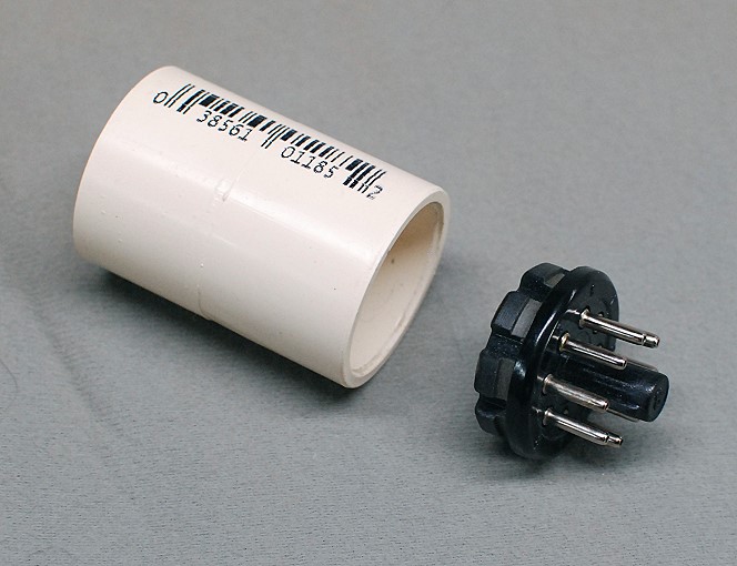 1" CPVC Coupling And 8-Pin Plug Click here for a larger image. |
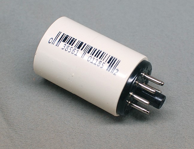 Plug Tightly Fitted Into Coupling Click here for a larger image. |
After installing the 8-pin plug, fit a round plastic or metal cap to the other end of the coupling to hold the RCA phono jack.Wire the center of the jack through the coupling capacitor to pin 5 of the octal plug. Wire the ground lead from the phono jack to pin 3 of the octal plug. Keep the connections as short as possible. I made a small aluminum cap on my lathe and held it in place with set screws. I also added set screws to the octal plug for extra strength. I am sure you can come up with something less fancy on your own. I also shortened the coupling so the jack wouldn't stick too far out of the front panel when plugged into the transmitter. I then wrapped the outer exposed end with black electrical tape for a more attactive look. See the photos below:
 VFO Input Adaptor Without Black Decorative Tape Click here for a larger image. |

VFO Input Adaptor With Black Decorative Tape Click here for a larger image. |
Plug the assembly into the octal crystal socket and set the Crystal/VFO switch to "XT1" to use your external VFO. Remember, your output frequency is either your VFO frequency or an integer multiple thereof, depending on the band. You can see my finished VFO adaptor installed in the photos below:

Ranger With VFO Adaptor Installed In Crystal Socket
Click on the image for a larger view.
Click here for a super detailed
view.
Speech Amplifier Capacitor C52
Replacement
There are many modifications of the audio system that can be found on the
internet and elsewhere. Most of these are wishful thinking, do not do as
claimed, or cause instability in the audio system.
Charles Rauch, W8JI, is one ham who really
knows his stuff. He has an excellent and extensive web site at
www.w8ji.com. On his web site he also has an
excellent page covering the various audio modifications to Ranger:
W8JI Ranger/Valiant
Audio Modifications Page
One conclusion that comes through loud and clear is that increasing the value
of C52, the
coupling capacitor between V7A and V7B, the mic preamplifier stages, from 500pf
to 0.01uf is about the only change in the audio system of any value.
This will bring the low frequencies up by several dB.
If you decide to do this, do not remove the original C52! Remember, you
are the steward of an antique, and want to keep changes reversible if possible.
Instead of removing C52, solder a new 0.01uf capacitor in parallel with it,
making sure that it can be easily removed in the future. This gives an
effective capacitance of 0.0105uf, which for all intents and purposes is the
same as 0.01uf.. The capacitor should be rated for at least 400V. Below is a
capacitor from Mouser Electronics that
will work fine:
0.01uf/400V film capacitor:
Mouser Part Number:
75-MKT1813310404
Personally, I have kept my audio section stock, with no modifications. I am
getting great audio reports with the original audio system and my D-104 mic,
and plan to use external equalization to fine tune my overall sound, if
I do anything at all.
Ordering Replacement Parts:
In spite of what many people think, parts and tubes for vintage equipment are
still readily available. One obvious source is hamfests, but there are two
other companies that I regularly deal with. They have always served me well.
The first company is Mouser Electronics.
Mouser is a huge parts supplier. Besides electronic parts they carry tools and
hardware, such as #4 to #10 screws, nuts, and lockwashers. They accept small
orders and they are happy to deal with a little guy like me. Shipping charges
are reasonable, and they have virtually every modern part you could want,
including high voltage electrolytic capacitors, big power resistors, etc. They
have a good search engine, but they carry so many components that it can take a
while to find what you want.
The other supplier is Antique Electronic
Supply. They are a much smaller company but specialize in parts for vintage
gear and guitar amplifiers, which are usually tube based. They carry tubes,
octal plugs, tube bases, tube sockets, and other vintage items.
Remember when replacing electrolytic capacitors in power supplies that
capacitors with reasonably higher higher voltage ratings and capacitances are
perfectly fine. For other capacitors, such as those in audio and RF circuits,
you should use the same value, but a higher voltage rating is fine. For power
resistors and pots, a larger power rating is also OK. Keep in mind that modern
components are much smaller than they were 50 years ago, which is a big
advantage. A 2W resistor today looks like a 1/2W resistor from 50 years ago, so
it is perfectly fine, for example, to use a 3W resistor to replace a 1W
resistor.
When ordering parts, try to consolidate your order and anticipate parts you
might need in the future. If in doubt, get the part anyway, because most parts
are relatively inexpensive, and it is the shipping/handling costs that tend to
increase the cost of a project. If you wind up not using the part it just goes
into your stock. I always make it a point to look around my shop and order some
extra parts to keep around, such as 0.001uf or 0.01uf capacitors, screws, nuts,
lockwashers, pilot lamps, etc.
Modifications Not Recommended:
The modifications that I recommend against are those that pervert the Ranger
into a different piece of equipment (such as total rebuilds of the audio
section), ruin the esthetic value or appearance of the transmitter, or
otherwise ruin the transmitter's value as an antique. I also recommend against
the internal PTT modification in the Ranger manual, because it extensively
modifies the Ranger, and it is easier to do the PTT
circuit externally. Remember, you are a temporary steward, and some day the
transmitter will be passed on to someone else. Make sure you leave something
worthy to pass on.
 Back to Dr. Greg Latta's
Electrical Engineering and Amateur Radio Pages
Back to Dr. Greg Latta's
Electrical Engineering and Amateur Radio Pages
 If you have any questions or
comments, you can send E-Mail to Dr. Greg Latta at
glatta@frostburg.edu
If you have any questions or
comments, you can send E-Mail to Dr. Greg Latta at
glatta@frostburg.edu