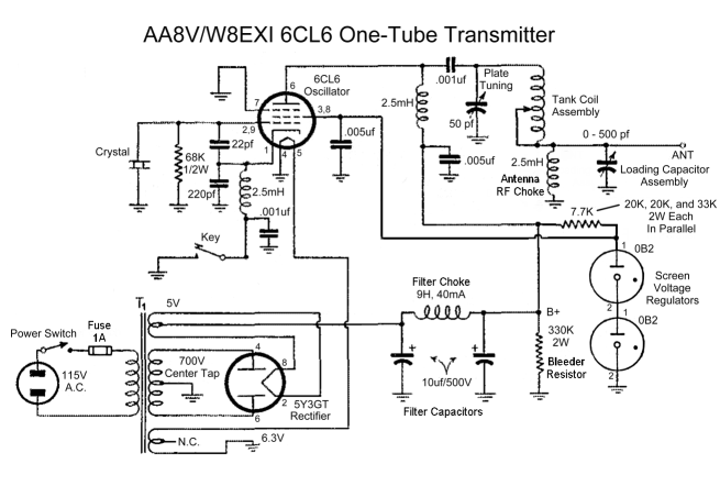

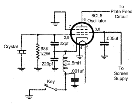
The operation of the 6CL6 transmitter is actually quite sophisticated, despite the simple appearance of the circuit. The heart of the circuit is the electron-coupled crystal oscillator shown above. This circuit combines the functions of oscillator and amplifier into a single tube, and provides excellent isolation between the oscillator and the output circuit. To understand the operation of an electron-coupled oscillator, consider first the triode oscillator shown below:
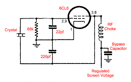
In this circuit the cathode is grounded and the screen grid of the tube is being used as the plate. (It is perfectly fine to use the screen grid as the plate, as long as the input is kept low enough so that the screen grid isn't damaged.) Feedback is obtained via the grid-plate capacitance of the tube and the 22pf and 220pf feedback capacitors. The crystal controls the frequency of oscillation. Rectified grid current through the 68k resistor provides bias for the tube. In this circuit, note that the cathode is grounded for RF and the plate (screen grid) is above ground for RF. The RF choke and bypass capacitor allow us to feed DC voltage to the screen while preventing the RF on the screen from getting into the power supply.
Let us now modify the previous circuit by moving the ground point for RF from the cathode of the tube to the screen grid (plate) of the tube and by adding a key, as shown in the circuit below:
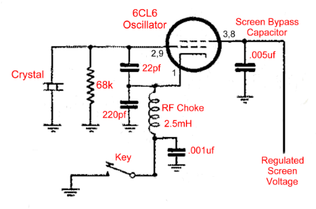
The .005uf screen bypass capacitor grounds the screen grid (plate) for RF while preventing the DC screen voltage from being shorted to ground. Meanwhile, the RF choke has been moved to the cathode lead so that the cathode can now float above ground for RF. Except for moving the ground point and adding the key, this circuit is identical to the previous. It is also identical to the circuit in the 6CL6 transmitter.
The problem with the above circuit is that there is no apparent output connection. It just appears to oscillate without doing anything useful! In reality, however, it is doing something very useful: it is producing an RF signal on the control grid of the tube. If we now apply a positive voltage to the real plate of the tube and draw current from the real plate of the tube, this current will be controlled by the signal on the control grid, and an amplified signal will appear on the real plate of the tube. Thus, the circuit oscillates and amplifies using the same tube! In summary: The screen grid, control grid, and cathode are used as a grounded screen (plate) crystal oscillator, while the cathode, control grid, and real plate are used as an amplifier. The control grid is the common element in the two circuits, and they are only coupled by the common electron stream within the tube. This is why the circuit is known as an "electron-coupled oscillator". The big bonus of this circuit is that the grounded screen grid shields the plate output circuit from the oscillator circuit, providing very good isolation between the two, especially when a well screened tube such as the 6CL6 is used. Without the electron-coupled circuit, tuning and load adjustments have a big effect on oscillator operation and keying, to the point that oscillation may actually stop at some settings of the tuning and load controls. With the electron-coupled circuit the impact of the tuning and load controls on the oscillator is greatly reduced. This means much better stability and keying, especially when a well screened tube, such as the 6CL6, is used.
| Quartz Crystal and Grid Leak: Though the feedback capacitors provide some of the feedback, the crystal also must do its part. The crystal is connected between the screen grid (oscillator plate, which is grounded) and control grid and represents a frequency dependent feedback path. As a result, feedback occurs only at the crystal frequency, and the resulting oscillations are at the crystal frequency. Rectified grid current flowing through the grid leak resistor produces a negative bias on the control grid of the tube. |
 |
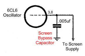
| Screen Bypass Capacitor: Like all bypass capacitors, the screen bypass capacitor provides a low impedance path for RF to ground. In other words, it grounds the screen for RF while preventing the DC screen voltage from being shorted to ground. The screen functions as the oscillator plate, so the oscillator is actually a grounded plate oscillator. |
 |
| Cathode and Keying Circuit: Since the oscillator is a grounded plate oscillator, it is necessary to keep the cathode of the tube above RF ground. This is done by placing an RF choke in the cathode lead. This permits direct current to flow to the cathode, while preventing any RF on the cathode from reaching ground. Any residual RF that gets through the choke is shorted to ground by the .001uf bypass capacitor. The key can open and close the DC return for the cathode, thus turning the oscillator on and off. |
 |
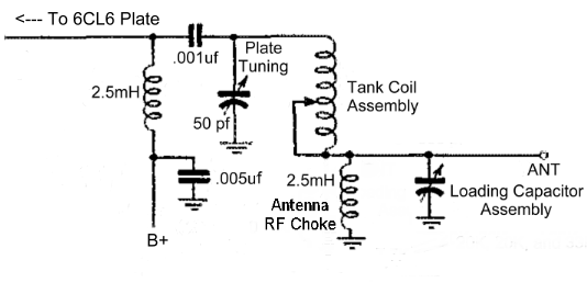
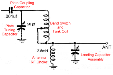
| Plate Tank Circuit: The plate tank circuit is a pi-network that matches the high impedance of the plate to the low impedance of the antenna. At the same time the circuit filters out undesired harmonics from the output signal. The signal from the plate enters through the .001 uf plate coupling capacitor. The 50 pf plate tuning capacitor tunes the plate to resonance. The band switch and tank coil provide the correct inductance for each band, and the 500 pf load capacitor (actually an assembly of switched fixed capacitors) adjusts the network for the best impedance match. The tank coil consists of 49 turns of #20 enameled wire, close wound on a 1.25 inch diameter coil form approximately 2 inches long. Taps are placed at 5 1/4 turns (15m), 10 1/4 turns (20m), 17 1/4 turns (30m), and 25 1/4 turns (40m) from the plate tuning capacitor end. All 49 turns are used on 80m. Click here for a tank coil schematic and tank coil winding information. The antenna RF choke is not necessary for the operation of the circuit, but is a safety feature. Without the choke, a short in the plate coupling capacitor would put the full B+ supply voltage on the antenna, a very dangerous situation. If the plate coupling capacitor were to short with the RF choke installed, the B+ supply would be shorted to ground, blowing the power supply fuse, and alerting the operator to a problem. |
|

| Power Supply Rectifier and
Transformer: The power supply transformer and rectifier produce a stream of high voltage pulsating DC that is then smoothed out by the power supply filter. The transformer steps up the 117 volts AC in the primary to 700 volts AC in the secondary. When the top connection to the secondary is positive with respect to the bottom connection and center tap, the upper diode of the 5Y3GT rectifier tube (pins 4 and 2/8) conducts, allowing current to pass to the output. During this time the bottom diode (pins 6 and 2/8) is cut off. When the bottom of the secondary is positive with respect to the top and center tap the opposite is true: the upper diode is cut off and the bottom diode conducts. The result is a stream of DC pulses at the output of the rectifier. The 5 volt secondary provides the 5 volts needed to heat the filament/cathode of the rectifier tube. Output from the rectifier is taken from the center tap on the 5 volt secondary. Click here for transformer specifications/requirements. |

|
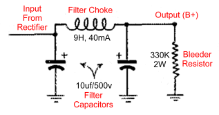
| Power Supply Filter: The output from the rectifier is direct current (DC) but with a large alternating current (AC) component superimposed. The power supply filter removes the AC component leaving the pure DC. The two filter capacitors are essentially an open circuit to the DC, but they effectively short circuit the AC component to ground. The filter choke on the other hand allows the DC component to flow through, while offering a very high impedance to the AC component. The result is that little of the AC component reaches the output. The bleeder resistor bleeds off the charge on the filter capacitors when the unit is shut off, preventing the possibility of a dangerous electric shock that could occur even though the unit were turned off and unplugged. The bleeder resistor also provides a minimum load on the power supply to prevent the output voltage from soaring during standby (key up) periods. |
 |
 Click here for pictures and information on the Wingfoot
VFO 2E26 Exciter
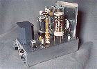 Click here for pictures and information on the Wingfoot
813 Amplifier
 Back to Dr.
Greg Latta's Electrical Engineering and Amateur Radio Pages
 If you have any questions or
comments, you can send E-Mail to Dr. Greg Latta at
glatta@frostburg.edu
This page is under constant revision. Please check back often.