
| 6AG7 Amplifier - Main Page and Exterior Photos | Tank Coil Construction Details |
| Interior Photos of the Finished Amplifier | Schematic Diagrams and Circuit Descriptions |
| Construction Photos | Testing And Preliminary Work |
| Typical Operating Conditions | Why Use A 6AG7? |
Introduction and Historical Background:
After using the 6CL6 One Tube
Transmitter and the 6146B amplifier
on the air for several years, I decided that it would be great to have VFO
control, rather than crystal control. Crystal control worked fine, but was
limiting. In particular, I found that many modern operators did not know that
they should tune up or down a few kHz after calling CQ, just in case someone
using crystal control was calling them back. The result was a fair number of
missed QSOs.
I had built an amplified digital VFO and had successfully interfaced it to my venerable Eico 720 transmitter. The combination worked beautifully, but I wanted to use the VFO with a homebrew transmitter, rather than a commercial transmitter. Plugging the output of my amplified DDS VFO into the crystal input of the 6CL6 transmitter (via a 1:4 transmission line transformer) worked well at driving the 6146B amplifier, but it was a compromise. The 6CL6 circuit was designed to be an oscillator, not an amplifier. It provided plenty of drive for the 6146B amplifier, but by itself it didn't give that much power out, and I wanted to run it barefoot as a QRP transmitter. I figured that I could probably get more power out if I designed a new one tube amplifier optimized for use with the DDS VFO. I could then use the VFO with the new amplifier as a QRP transmitter, or I could add the 6146B amplifier for higher power.
Remembering that I had a small crystal oscillator transmitter in a corner of the shop that might serve as the basis for the new amplifier, I began testing and preliminary work to see if I could use the little transmitter as the basis for a new amplifier. After much experimentation and a total rebuild on a new chassis, the result is the 6AG7 amplifier that you see in these pages.
Overall View: In this view of the amplifier the power transformer and 5Y3 rectifier are in the back, and the 6AG7 and other components are towards the front. The 6AG7 is the black metal tube in the middle of the chassis. The chassis is actually a 9 inch cake pan, in keeping with the tradition of many homebrew transmitters built in the 1950s and 1960s. The cake pan came painted with an attractive, durable finish, and I can't imagine a better or more attractive chassis for the amplifier. |
Click on the image for a larger view. Click here for a super detailed view. |
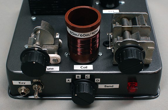
Front Close Up View: The 6AG7 amplifier is a band switching amplifier that uses two plug in coils. The band switch is in the center of the front panel and has four positions, so a single coil form can actually accommodate four different bands. More inductance is switched in as the switch is rotated counterclockwise from D to A. I am currently using the amplifier on five bands, so I used one coil to cover three bands and another to cover the two remaining bands. The coil visible in the photo covers the 80m, 60m, and 40m bands, and another coil covers the 30m and 20m bands. As in many other tube amplifiers, a pi network is used to match the output of the tube to the antenna. The plate tuning capacitor is on the left, the tank coil is in the center, and the loading capacitor is on the right. The key jack is at the lower left, and the power switch is just to the right of the key jack. The pilot light on the right indicates when the amplifier is turned on. |
Click on the image for a larger view. Click here for a super detailed view. |
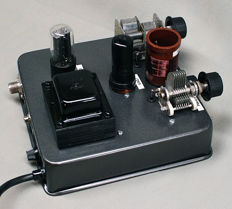
Side View: In this side view of the amplifier the rear panel is to the left and the front is to the right. The rear panel contains a fuse holder and the input and output connectors. The 5Y3 rectifier tube is behind the power transformer on the left. The 6AG7 tube can be clearly seen near the middle of the chassis. The loading capacitor is at the upper right and the plate tuning capacitor is at the lower right. Connections to the plate tuning and loading capacitors are made through grommeted holes in the chassis. These can be seen just above and below the left side of the coil in the photo. |
 Click on the image for a larger view. Click here for a super detailed view. |
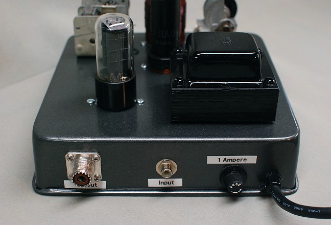
Rear Close Up View: This is a rear view of the 6AG7 amplifier. On the top of the amplifier are the 5Y3 rectifier tube on the left and the Stancor P-6010 power transformer on the right. The transformer was cleaned and then airbrushed with gloss black Rustoleum to restore its original appearance. The rear panel contains an SO-239 coaxial connector for the output on the left and an RCA phono connector for the input at center. The 1 Ampere fuse on the right protects the power supply in case of component failure, and a strain relief is used to protect the grounded power cord. The chassis is a 9" square cake pan with a very durable finish that I obtained from the local surplus store. Many homebrew transmitters from the 1950s and 1960s used cookware for the chassis, since the chassis was usually one of the most expensive parts of a project. |
 Click on the image for a larger view. Click here for a super detailed view. |
 Click here for pictures and information on the matching
6146B Linear Amplifier
Click here for pictures and information on the matching
6146B Linear Amplifier Click here for pictures and information on the Wingfoot
VFO 2E26 Exciter
Click here for pictures and information on the Wingfoot
VFO 2E26 Exciter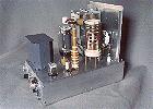 Click here for pictures and information on the Wingfoot
813 Amplifier
Click here for pictures and information on the Wingfoot
813 Amplifier Back to Dr.
Greg Latta's Electrical Engineering and Amateur Radio Pages
Back to Dr.
Greg Latta's Electrical Engineering and Amateur Radio Pages
 If you have any questions or
comments, you can send E-Mail to Dr. Greg Latta at
glatta@frostburg.edu
If you have any questions or
comments, you can send E-Mail to Dr. Greg Latta at
glatta@frostburg.edu